5 ARENA
The
The
Illustrations included in this section are for a general visual understanding of the RAPID REACT
5.1 FIELD
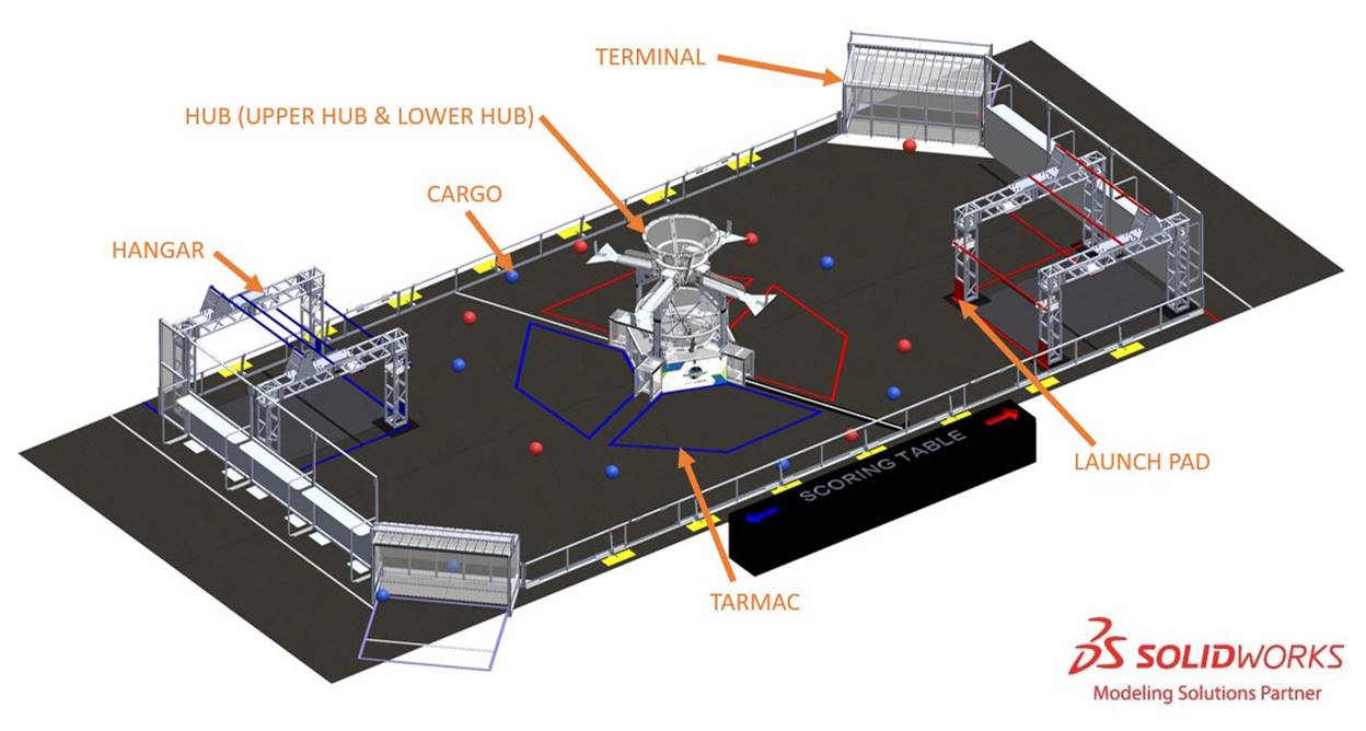
Each
The
- 1 (including 1HUBand 1UPPER HUB),LOWER HUB
- 2 (a redHANGARSand a blueHANGAR),HANGAR
- 2 , andTERMINALS
- 14 . The surface of theCARGO RINGSis low pile carpet, Shaw Floors, Philadelphia Commercial, Neyland II 20, “66561 Medallion” (please note that Neyland II carpet is not available for team purchase and the closest equivalent is Neyland III). The edge of the carpet is secured to the venue floor using 3M™ Premium Matte Cloth (Gaffers) Tape GT2 or comparable gaffers tape.FIELD
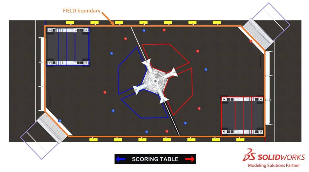
Guardrails form the long edges of the

There are 2 versions of guardrails and
A run of black HDPE cable protectors extends from the guardrail on the scoring table side of the
5.2 Zones and Markings
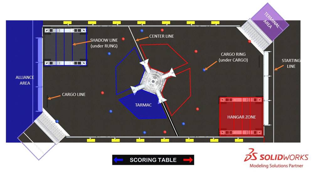
- : a 30 ft. (~914 cm) wide by 8 ft. 10 in. (~269 cm) deep infinitely tall volume formed by, and including theALLIANCE AREA, the edge of the carpet, andALLIANCE WALLcolored tape. It includes neither theALLIANCEnor theTERMINAL AREA.TERMINAL
- : a 3 ft. (~91 cm) black line that starts 1 ft. (~30 cm) from the intersection of theCARGO LINEand theTERMINALand runs parallel to and 1 ft. (~30 cm) from theALLIANCE WALL.ALLIANCE WALL
- : 1 of 14 small rings used to keep theCARGO RINGin place prior to the start of theCARGO. Rings are ⅛ in. (~3mm) thick, 1¾ in. (~4 cm) diameter O-rings (McMaster Item#: 9452K63). 12 rings are placed around theMATCH, and 1 ring is in front of eachHUB. They are secured toTERMINALcarpet with red or blue tape to indicate the colorFIELDto be placed on it.CARGO
- : a white line that bisects the length of theCENTER LINEat a ~66° angle to the guardrailFIELD
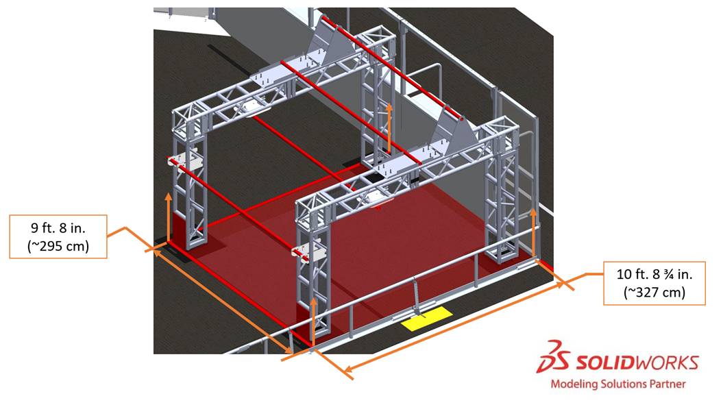
- : a 9 ft. 8 in. (~295 cm) wide, 10 ft. 8¾ in. (327 cm) deep, and infinitely tall volume defined by theHANGAR ZONE, guardrail, andALLIANCE WALLcolored tape. TheALLIANCEincludes the tape.HANGAR ZONE
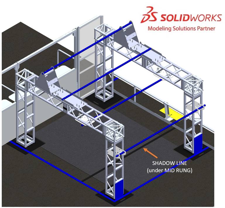
- : a black line that lies directly below theSHADOW LINEMID RUNG
- : a white line spanning the width of the carpet and located 2 ft. 4 in. (~71 cm) from the back of theSTARTING LINEdiamond plate panel to the near edge of the tape.DRIVER STATION
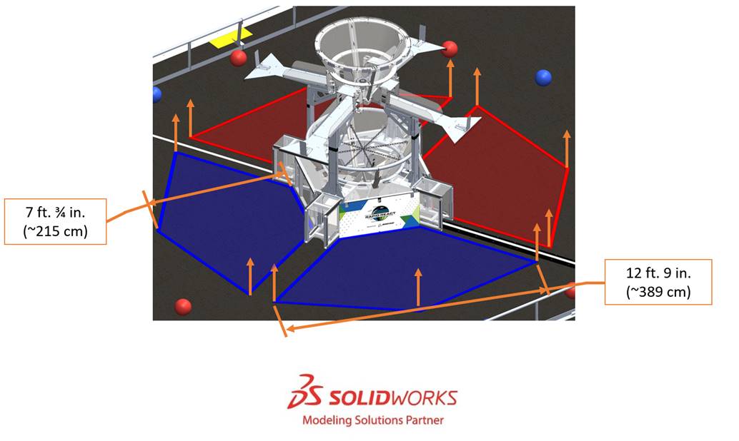
- : 1 of 4 (2 perTARMAC) 12 ft. 9 in. (~389 cm) wide by 7 ft. ¾ in. (~215 cm) deep infinitely tall volumes bounded by and including theALLIANCEcolored tape.ALLIANCE
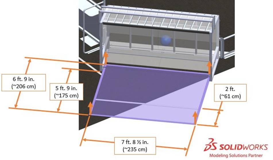
- : 1 of 2 7 ft. 8½ in, (~235 cm) wide by 6 ft. 9 in. (~206 cm) deep and infinitely tall volumes bounded by and including purple tape.TERMINAL AREA
- : a white line spanning the width of theTERMINAL STARTING LINEand located 2 ft. (~61 cm) from the back of theTERMINAL AREA.TERMINAL AREA
5.3 HUB
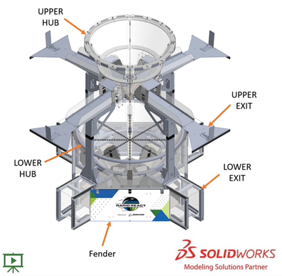
The
An agitator extends up the center of each
An
4 legs, each centered under an
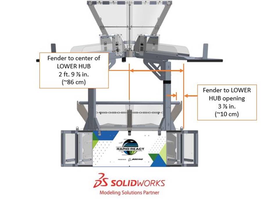
5.3.1 UPPER HUB and LOWER HUB
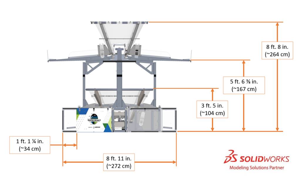
The opening of the
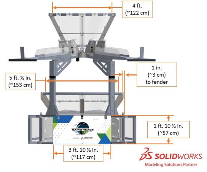
The
5.3.2 Fenders
Fenders are 3 ft. 10⅛ in. (~117 cm) wide by 1 ft. 10½ in. (~57 cm) tall, are positioned between each
5.4 HANGARS
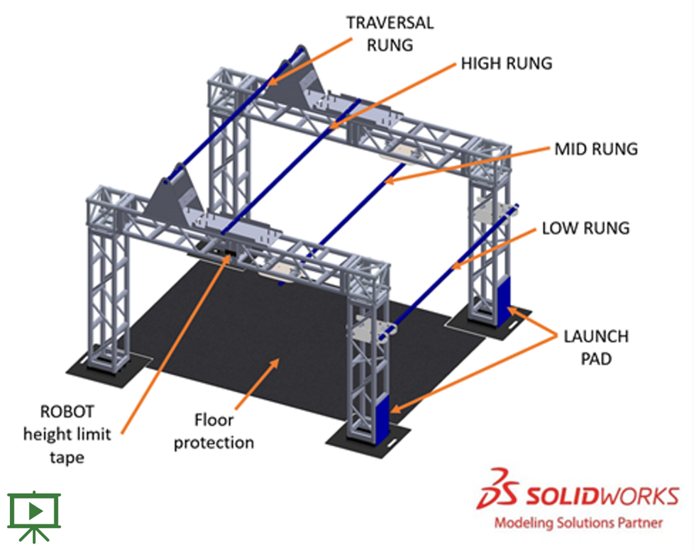
A
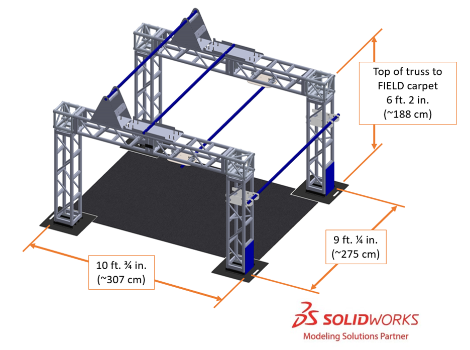
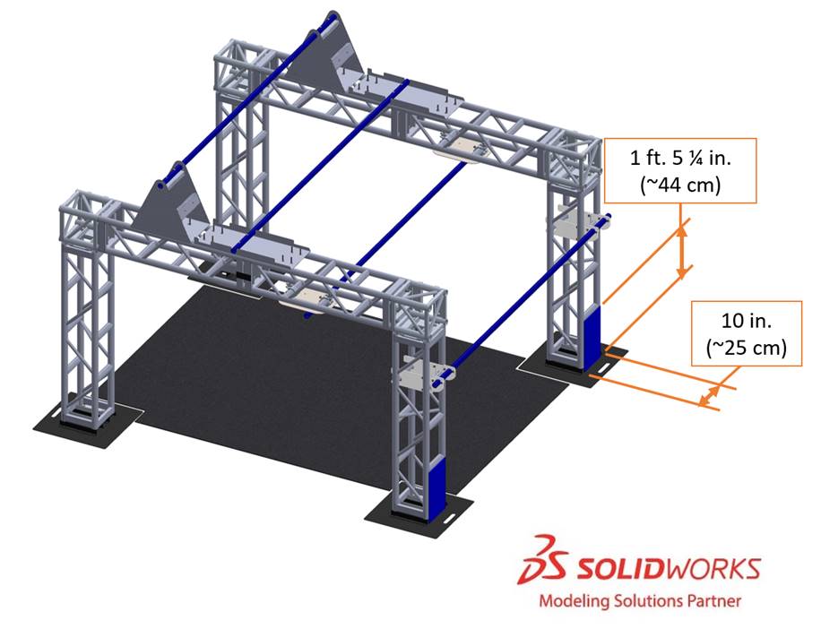
5.4.1 Truss Structure
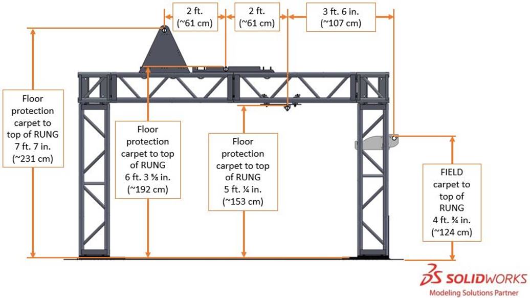
5.4.2 Rungs
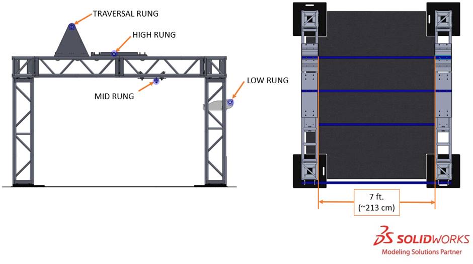
Each
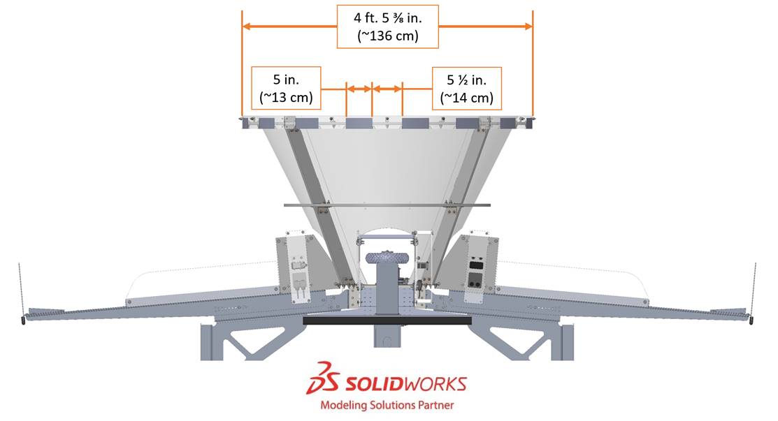
Figure 5‑17 illustrates spacing between
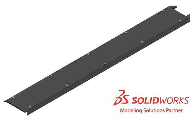
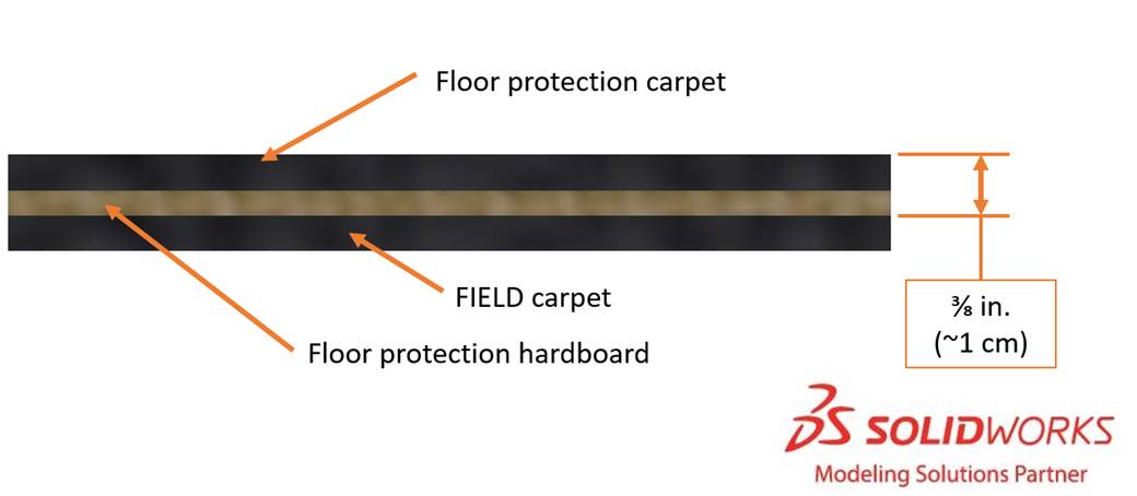
5.4.3 Floor Protection
A layer of ⅛ in. (~3 mm) thick hardboard is installed on top of the
5.4.4 LAUNCH PADS
5.5 TERMINALS
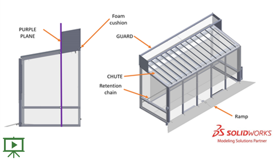
One
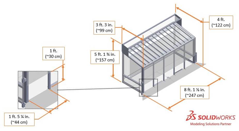
Each
A 2¾ in. (~7 cm) tall ramp leads to the 1 ft. 5¼ in. (~44 cm) wide, 1 ft. (~30 cm) tall openings.
The
The
A
The
5.6 ALLIANCE WALLS
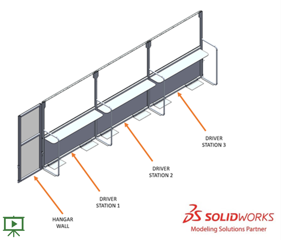
An
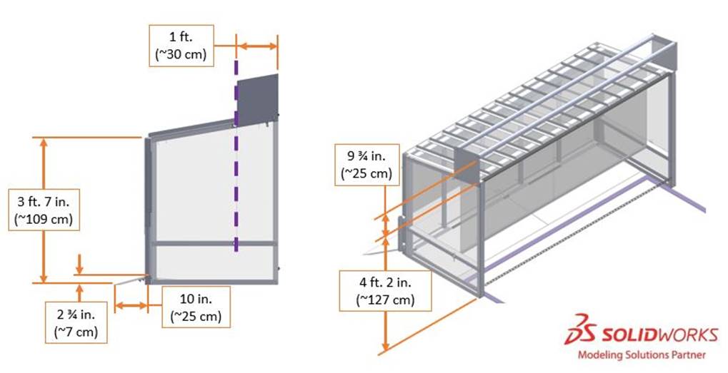
5.6.1 DRIVER STATIONS
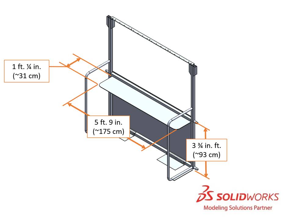
A
Each
- 1 Ethernet cable: attaches to the Ethernet port of the and provides connectivity to theOPERATOR CONSOLEManagement System (Field)FMS
- 1 120VAC NEMA 5-15R power outlet (i.e. standard US outlet): located on each shelf and protected by its own 2-Amp circuit breaker. It can be used to power theDRIVER STATION.OPERATOR CONSOLEare responsible for monitoring their power consumption as a tripped breaker in the outlet does not constitute anDRIVE TEAMS. For some events in regions that don’t use NEMA 5-15 shaped outlets, event organizers may install appropriate plug adapters to be used throughout the event.ARENA FAULT
- 1 Emergency Stop (E-Stop) button: located on the left side of the shelf and is used to deactivate aDRIVER STATIONin an emergencyROBOT
- 1 team sign: displays the team number and located at the top of each DRIVER STATION
- 1 team LED stack: indicates color,ALLIANCEstatus, E-Stop status, and is centered at the top of eachROBOT.DRIVER STATION
The stack includes 2 identical ALLIANCE-colored
- status LEDs Solid: indicates that theROBOTis connected and enabled. This only happens during aROBOT. Blinking: indicates that either theMATCHis preset for theFMSand theMATCHis not connected yet, or it’s during aROBOTand the correspondingMATCHisROBOT, has lost connectivity, or the E-stop was pressed. Off: indicates that theBYPASSEDis linked andROBOTprior to the start of theDISABLED. This light is also off, regardless ofMATCHconnection status, after theROBOThas concluded. E-stop LED Solid: theMATCHisROBOTdue to a press of the team E-stop button, theDISABLEDE-stop button, or by the scorekeeper via theFIELD. Off: theFMSis notROBOTby theDISABLED.FIELD
- 1 string of LED nodes described in Section 5.6.1.1 LED Strings.Driver Station
- 1 timer (in 2 only): displays the official time remaining in theDRIVER STATIONandMATCH. It is marked with white tape along the bottom edge.TIMEOUTS
- hardware and wiring: mostly located below theFMS2 shelfDRIVER STATION
5.6.1.1 DRIVER STATION LED Strings
A string of LED nodes is mounted to the bottom of each
If the light string is all green, the

During a
If an


If the

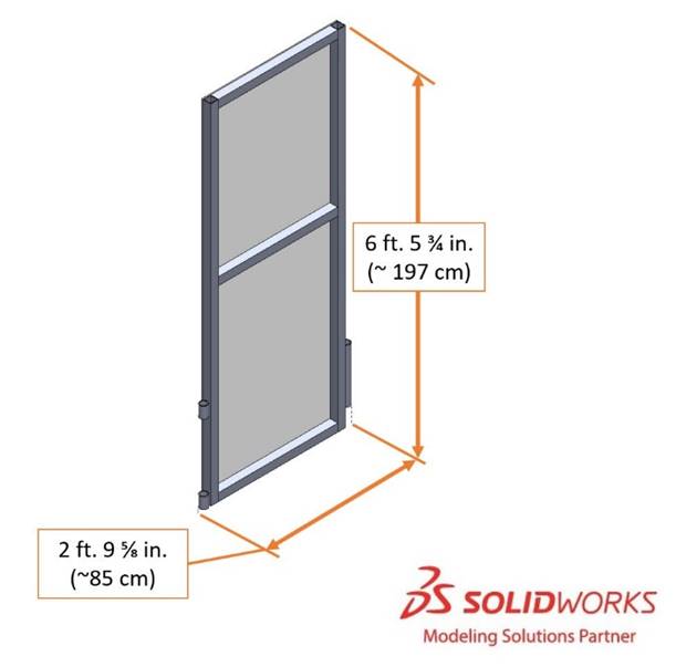
5.6.2 HANGAR WALLS
A
5.7 CARGO

RAPID REACT is played with oversized tennis balls called
5.8 Vision Targets
The
5.9 The FIELD Management System
The
When a
Note that
The
| Event | Timer Value | Audio Cue |
|---|---|---|
MATCH | 0:15 (for AUTO | “Cavalry Charge” |
AUTO | 0:00 (for AUTO | “Buzzer” |
TELEOP | 2:15 | “3 Bells” |
HANGAR ZONE | 0:30 | “Train Whistle” |
MATCH | 0:00 | “Buzzer” |
MATCH | n/a | “Foghorn” |
TIMEOUT | 1:00 | “Trumpet Fanfare” |
TIMEOUT | 0:00 | “Buzzer” |