

5 ARENA
The
The
Illustrations included in this section are for a general visual understanding of the CHARGED UP
5.1 FIELD
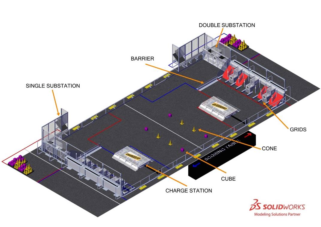
Each
The
- 3 red and 3 blueGRIDSlocated in front of their correspondingGRIDS,ALLIANCE WALLS
- 1 red and 1 blueCHARGE STATIONlocated in their corresponding COMMUNITIES,CHARGE STATION
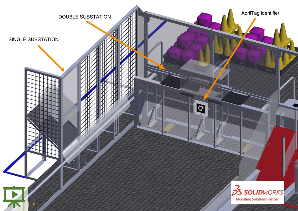
- 1 red and 1 BlueSINGLE SUBSTATIONlocated along the guardrail in their correspondingSINGLE SUBSTATIONAREA,SUBSTATION
- 1 red and 1 blueDOUBLE SUBSTATIONeach located in line with and adjacent to the opposingDOUBLE SUBSTATIONALLIANCE WALL
- 2 , 1 separating eachBARRIERSfrom the opposingCOMMUNITY’SALLIANCE.LOADING ZONE
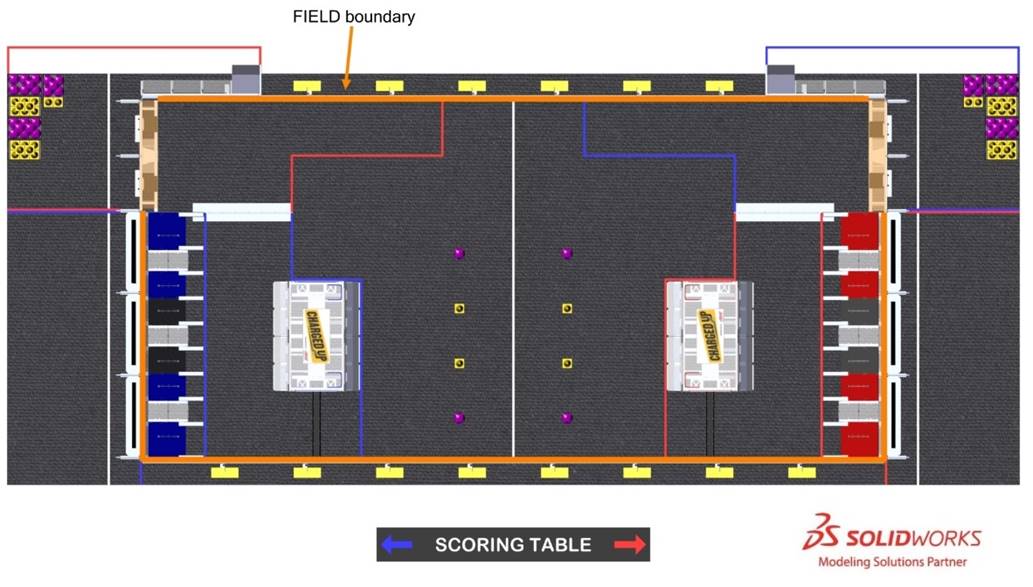
The surface of the
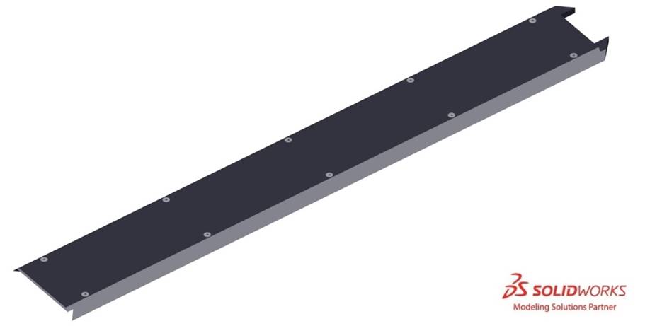
Guardrails form the long edges of the
There are 2 versions of guardrails and
Runs of black HDPE cable protectors extend from the guardrail on the scoring table side of the
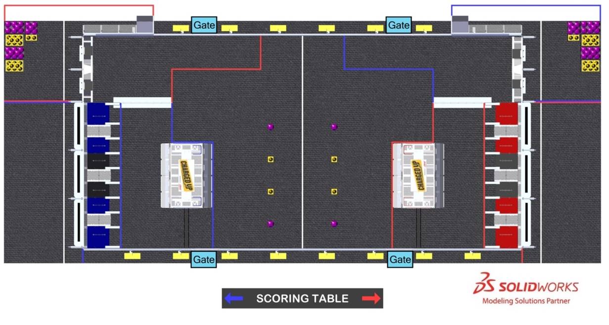
5.2 Areas, Zones, and Markings
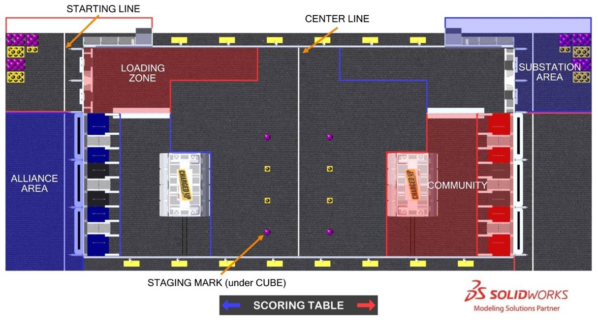
- : a 20 ft. (~609 cm) wide by 9 ft. 10¼ in. (~300 cm) deep infinitely tall volume formed by, and including theALLIANCE AREA, the edge of the carpet, andALLIANCE WALLcolored tape.ALLIANCE
- : a white tape line that bisects the length of theCENTER LINE.FIELD
- : an 18 ft. (~549 cm) wide by 11 ft. ⅜ in. (~336 cm) to 16 ft. 1¼ in. (~491 cm) deep infinitely tall volume formed by theCOMMUNITY, the plane defined by theALLIANCE WALLplastic,BARRIERcolored tape, and the guardrail. TheALLIANCEincludes the tape.COMMUNITY
- : an 8 ft. 3 in. (~252 cm) wide by 11 ft. ¼ in. (~336 cm) to 22 ft. ¼ in. (~671 cm) deep infinitely tall volume formed by theLOADING ZONE, the plane defined by theDOUBLE SUBSTATIONplastic, the guardrail, andBARRIERcolored tape. TheALLIANCEincludes the tape.LOADING ZONE
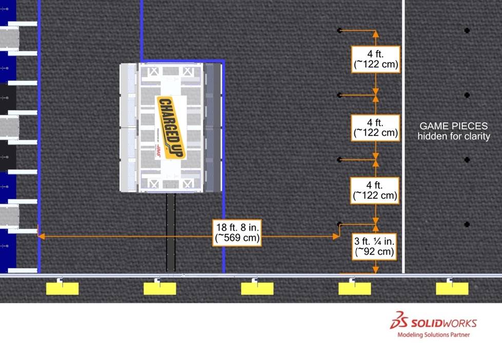
- : 1 of 8 marks used to identify starting locations forSTAGING MARK. Marks are 4 in. (~10 cm) by 4 in. (~10 cm) crosses made from black tape. Marks are spaced 4 ft. (~122 cm) apart from each other. Each set of 4 marks is centered about the width of theGAME PIECESand is located 18 ft. 8 in. (~569 cm) from the far edge of the correspondingCOMMUNITYtape as shown in Figure 5‑7. A small, light mark may be added to eachGRIDto distinguishSTAGING MARKfrom black tape used to patch carpet.STAGING MARKS
- : a white tape line spanning theSTARTING LINEandALLIANCE AREAAREA located 2 ft. 4 in. (~71 cm) from the face of theSUBSTATIONto the near edge of the tape.ALLIANCE WALL
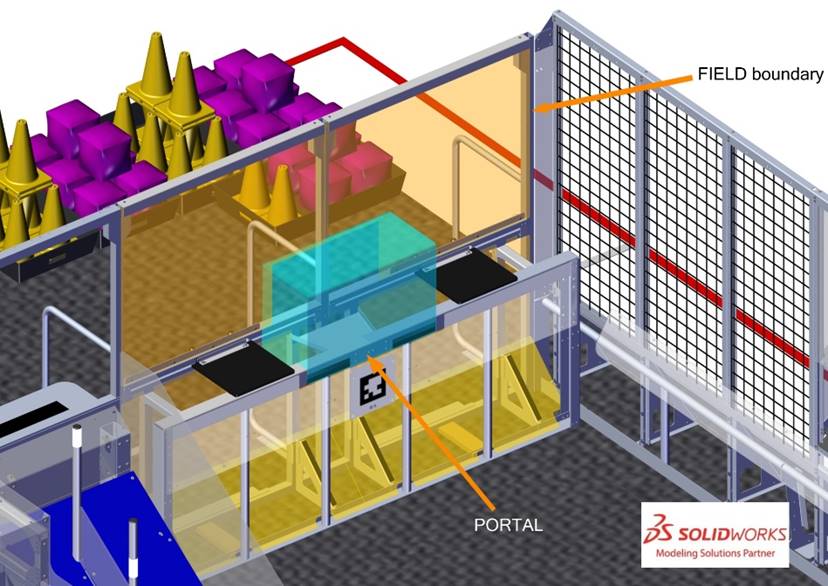
- AREA: a 12 ft. (~366 cm) wide by 18 ft. 7 in. (~566 cm) deep infinitely tall volume formed by and including theSUBSTATION, the edge of the carpet, the guardrail, theDOUBLE SUBSTATIONandSINGLE SUBSTATIONcolored tape. TheALLIANCEAREA includes theSUBSTATIONand the tape.PORTALS
5.3 BARRIER
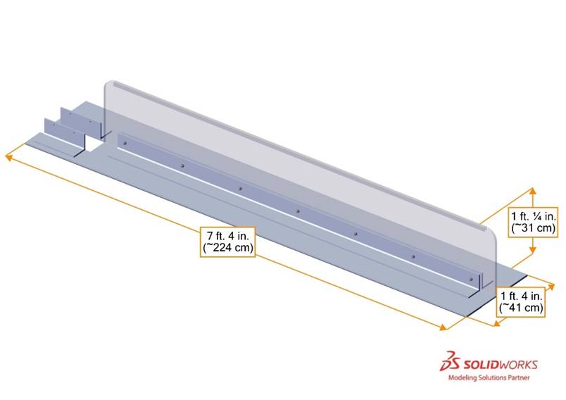
A
5.4 CHARGE STATION
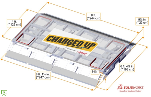
A
The main pivoting surface of a
Polycarbonate ramps are located on the long edges of each
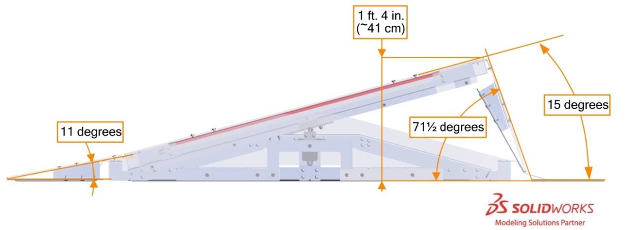
The short edges of the
5.4.1 CHARGE STATION lighting
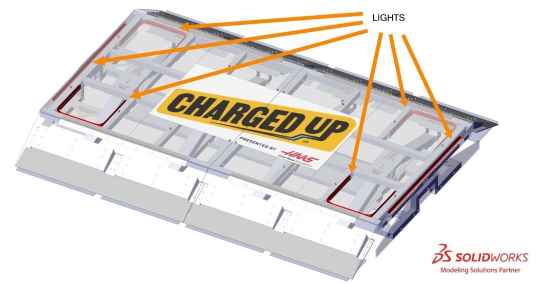
| Light State | Criteria |
|---|---|
| Off | Outside of a MATCH MATCH CHARGE STATION LEVEL |
ALLIANCE | CHARGE STATION LEVEL |
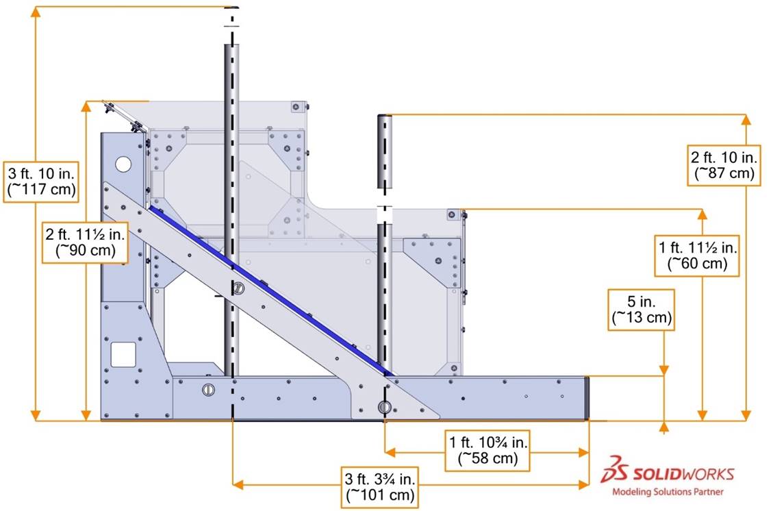
5.5 GRIDS
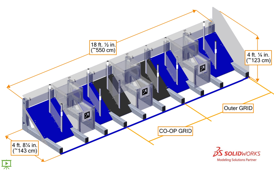
A collection of 3
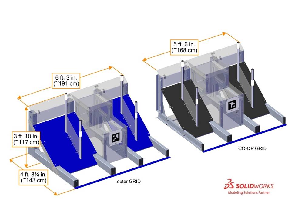
A
Each
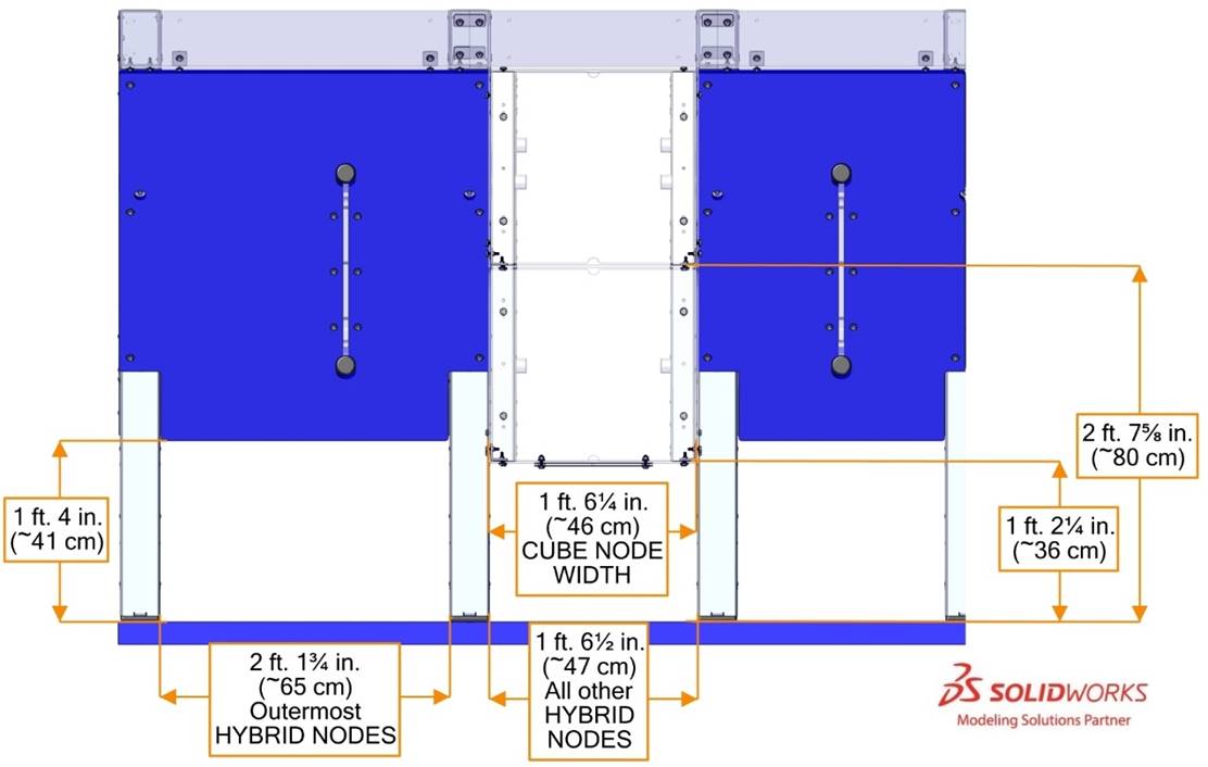
- 3 HYBRID NODES
- 2 , andCUBE NODES
- 4 .CONE NODES
Each set of
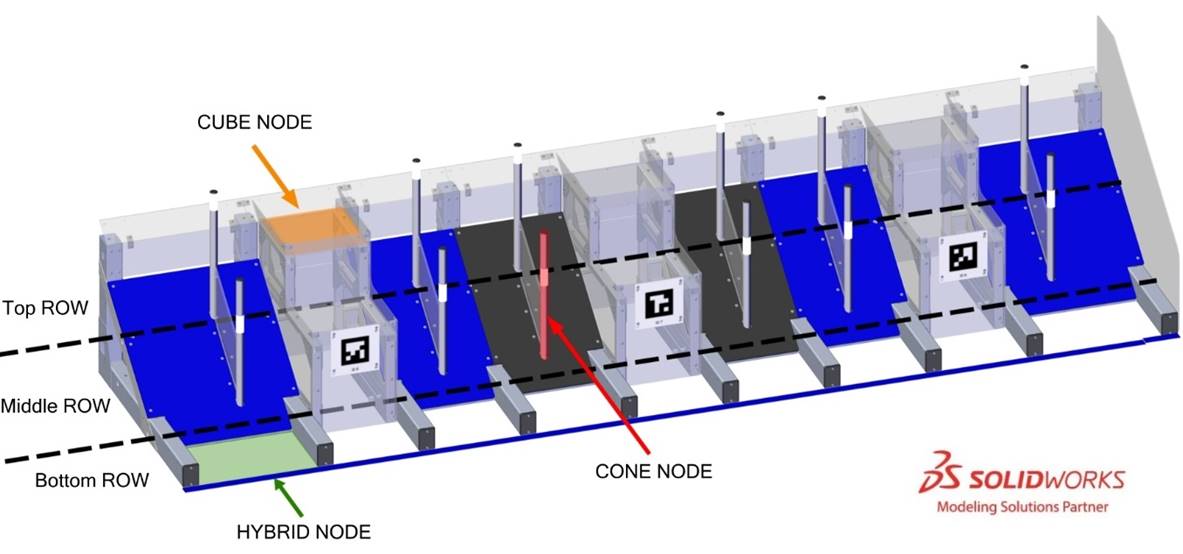
A
Each
Each
5.6 SUBSTATIONS
A
Each
We recognize that some individuals may need an accommodation in order to use the
Each
5.6.1 SINGLE SUBSTATION
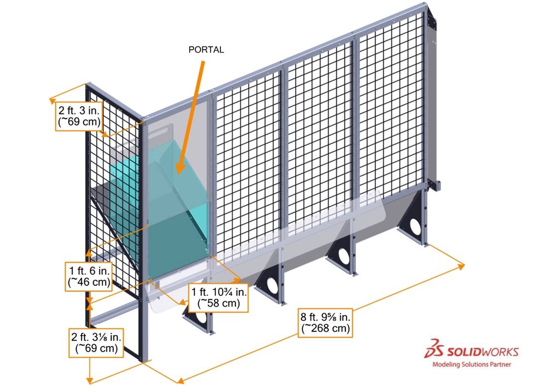
A
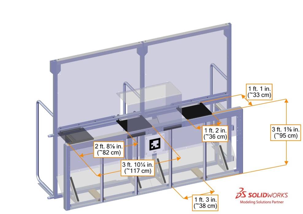
5.6.2 DOUBLE SUBSTATION
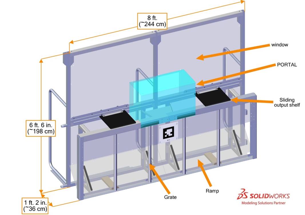
A
Grate openings are defined by 1¼ in. schedule 40 aluminum pipes which have an outer diameter of 1.66 in. (~4 cm). The distance between pipes is 1 ft. 3 in. (~38 cm). A polycarbonate ramp spans the width of the
The
Sliding shelves made of ½ in. (~13 mm) thick textured HDPE may be used to move
Each
5.7 ALLIANCE WALLS
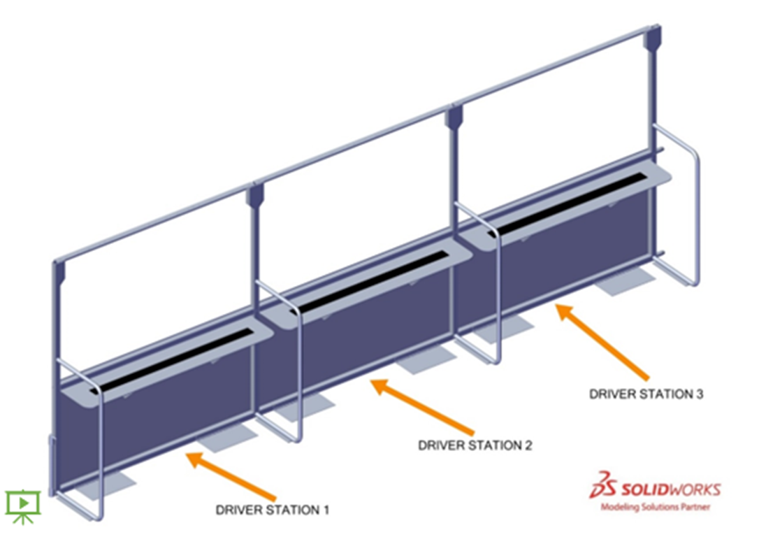
The
5.7.1 DRIVER STATIONS
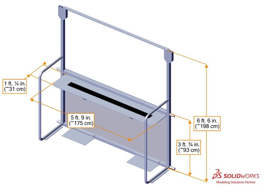
A
There may be a ramp available at events for
This ramp is available at many Regional and District events. For questions please connect with the local Program Delivery Partner.
Each
- 1 Ethernet cable: attaches to the Ethernet port of the and provides connectivity to theOPERATOR CONSOLEManagement System (Field)FMS
- 1 120VAC NEMA 5-15R power outlet (i.e. standard US outlet): located on each shelf and protected by its own 2-Amp circuit breaker. It can be used to power theDRIVER STATION.OPERATOR CONSOLEare responsible for monitoring their power consumption as a tripped breaker in the outlet does not constitute anDRIVE TEAMS. For some events in regions that don’t use NEMA 5-15 shaped outlets, event organizers may install appropriate plug adapters to be used throughout the event.ARENA FAULT
- 1 Emergency Stop (E-Stop) button: located on the left side of the shelf and is used to deactivate aDRIVER STATIONin an emergencyROBOT
- 1 team sign: displays the team number and located at the top of each DRIVER STATION
- 1 team LED stack: indicates color,ALLIANCEstatus, E-Stop status, and is centered at the top of eachROBOT.DRIVER STATION
The stack includes 2 identical ALLIANCE-colored
- status LEDs Solid: indicates that theROBOTis connected and enabled. This only happens during aROBOT. Blinking: indicates that either theMATCHis preset for theFMSand theMATCHis not connected yet, or it’s during aROBOTand the correspondingMATCHisROBOT, has lost connectivity, or the E-stop was pressed. Off: indicates that theBYPASSEDis linked andROBOTprior to the start of theDISABLED. This light is also off, regardless ofMATCHconnection status, after theROBOThas concluded. E-stop LED Solid: theMATCHisROBOTdue to a press of the team E-stop button, theDISABLEDE-stop button, or by the scorekeeper via theFIELD. Off: theFMSis notROBOTby theDISABLED.FIELD
- 1 string of LED described innodesLED Strings.DRIVER STATION
- 1 timer (in 2 only): displays the official time remaining in theDRIVER STATION. It is marked with white tape along the bottom edge.MATCH
- hardware and wiring: mostly located below theFMS2 shelfDRIVER STATION
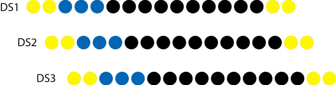
5.7.1.1 DRIVER STATION LED Strings
A string of LED
If the light string is all green, the
| Light String State | Criteria | Example |
|---|---|---|
| Off | Outside of a MATCH FIELD MATCH GAME PIECE | |
| Green | Head REFEREE FIELD | |
ALLIANCE DRIVER STATION | LINK LINK LINKS | |
| 4 outer nodes | DOCKED ENGAGED AUTO | |
ALLIANCE nodes | SUSTAINABILITY BONUS | |
| Magenta color (fills left to right, center DRIVER STATION | COOPERTITION BONUS | |
| White | within 3 seconds of the ending of AUTO TELEOP | |
| Oscillating ALLIANCE | Start of ENDGAME | |
| 5 center nodes | Set of ALLIANCE GRIDS |
Light patterns layer as
5.8 GAME PIECES
There are 2 types of
5.8.1 CONE
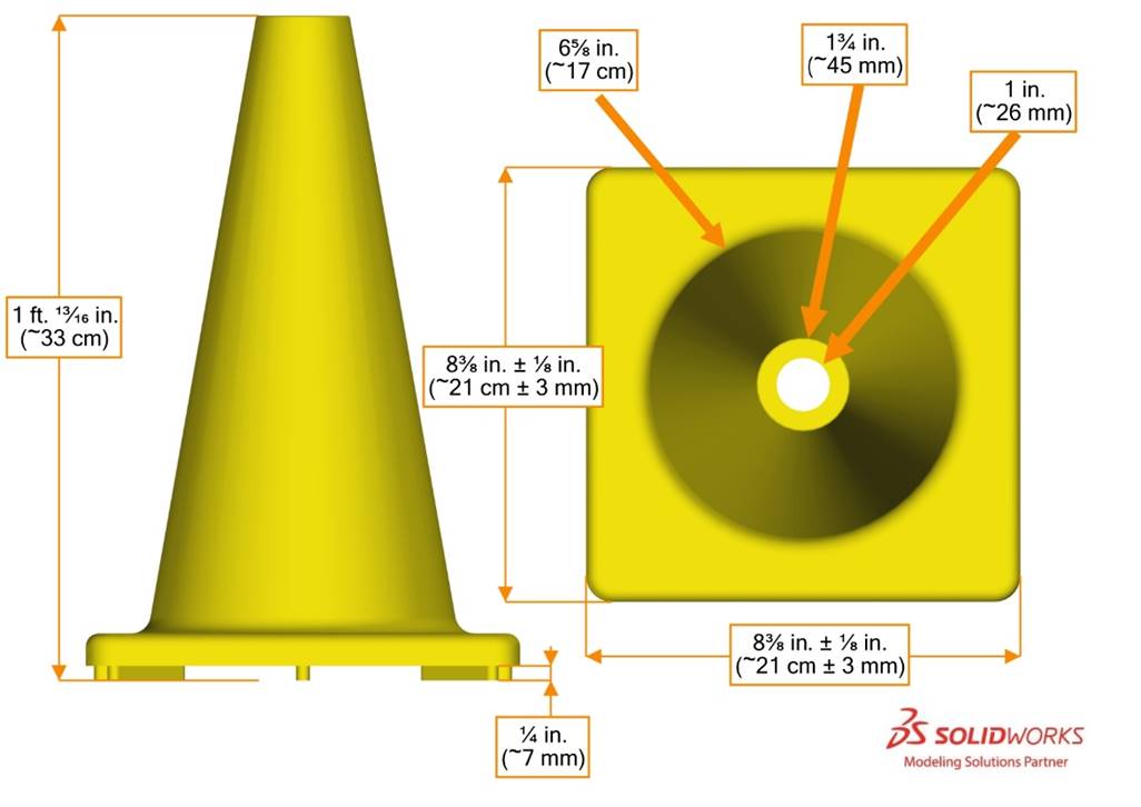
Each
5.8.2 CUBE
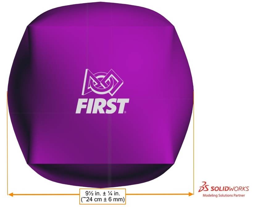
Each
Note that Flaghouse part number 17810 is not identical to a
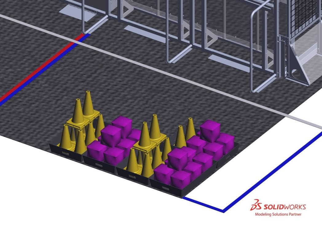
5.8.3 GAME PIECE Holders
5.9 Vision Targets
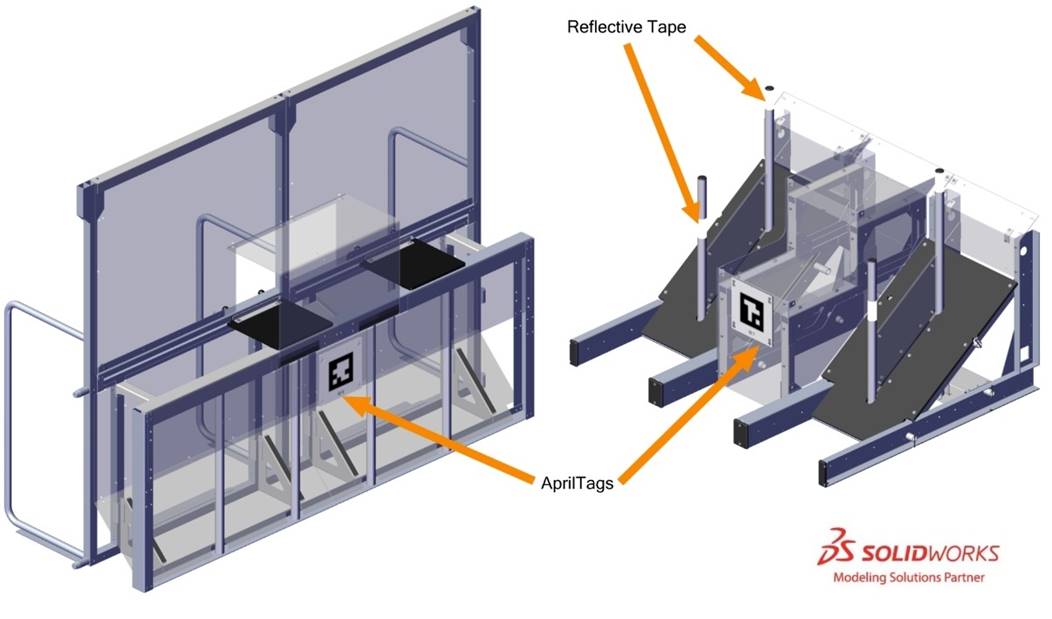
Vision targets are located on each
· reflective tape, and
· AprilTags.
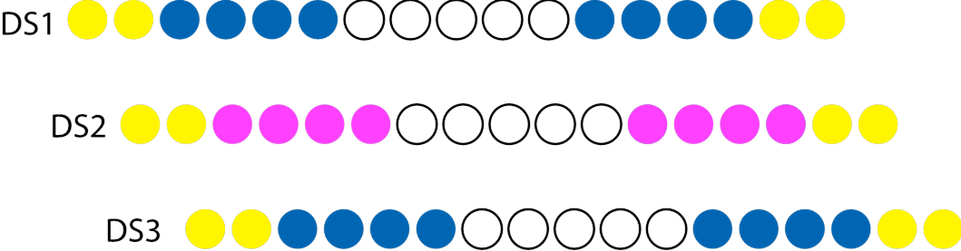
Samples of the reflective tape material are included in each Kickoff Kit.
5.9.1 Reflective Tape
Reflective tape vision targets are made of 2 in. (~5 cm) thick strips of 3M 973-10 Diamond Grade Flexible Prismatic School Bus Marking Series White and are used to highlight each
A 4 in. (~10 cm) tall portion of each
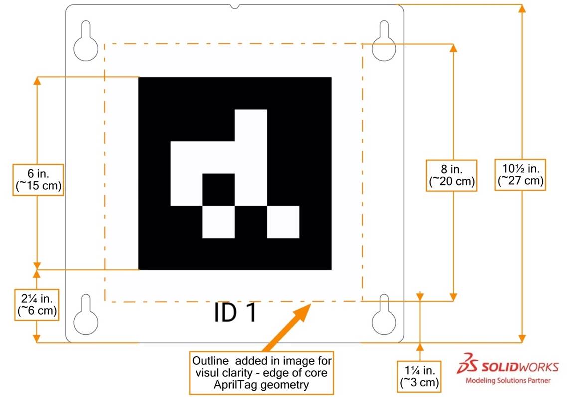
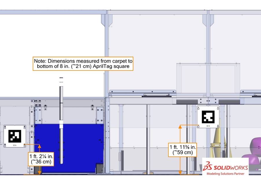
5.9.2 AprilTags
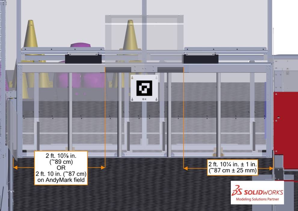
AprilTags are 8 in. (~20 cm) square targets located on the
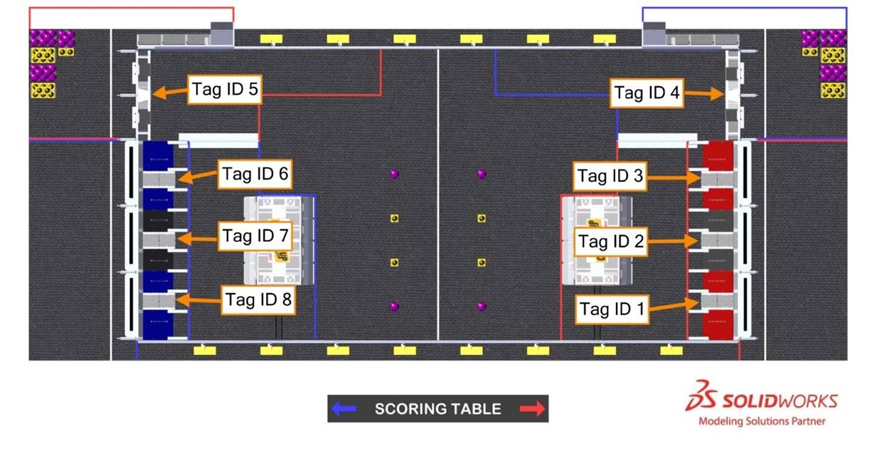
All markers are from the 16h5 tag family, IDs 1-8. AprilTags are mounted to and centered on a 10½ in. (~27 cm) square piece of polycarbonate. The 8 in. (~20 cm) tag is centered on the polycarbonate panel, such that the bottom of the central black square region is 2¼ in. (~6 cm) from the bottom of the panel, and the bottom of the 8 in. (~20 cm.) tag is located 1 ¼ in. (~3 cm) from the bottom of the panel as shown in Figure 5‑32. Each marker has an identifying text label.
AprilTags are likely to experience wear and marking during
For further marker locating information please refer to the 2023
5.10 The FIELD Management System
The
When a
Note that
The
| Event | Timer Value | Audio Cue |
|---|---|---|
MATCH | 0:15 (for AUTO | “Cavalry Charge” |
AUTO | 0:00 (for AUTO | “Buzzer” |
TELEOP | 2:15 | “3 Bells” |
| ENDGAME begins | 0:30 | “Train Whistle” |
MATCH | 0:00 | “Buzzer” |
MATCH | n/a | “Foghorn” |
