

9 ROBOT Construction Rules
The rules listed below explicitly address legal parts and materials and how those parts and materials may be used on a CHARGED UP
There are many reasons for the structure of the rules, including safety, reliability, parity, creation of a reasonable design challenge, adherence to professional standards, impact on the competition, and compatibility with the Kit of Parts (
Another intent of these rules is to have all energy sources and active actuation systems on the
Many rules in this section reference Commercial-Off-The-Shelf (
Example 1: A team orders 2
Example 2: A team obtains openly available blueprints of a drive module commonly available from Wheels-R-Us Inc. and has local machine shop “We-Make-It, Inc.” manufacture a copy of the part for them. The produced part is not a
Example 3: A team obtains openly available design drawings from a professional publication during the pre-season and uses them to fabricate a gearbox for their
Example 4: A
Example 5: A team has a
Example 6: A team has a
A
- A. has a Federal Tax Identification number. In cases where the is outside of the United States, they must possess an equivalent form of registration or license with the government of their home nation that establishes and validates their status as a legitimate business licensed to operate within that country.VENDOR
- B. is not a “wholly owned subsidiary” of a FIRST Robotics Competition team or collection of teams. While there may be some individuals affiliated with both a team and the , the business and activities of the team andVENDORmust be completely separable.VENDOR
- C. should maintain sufficient stock or production capability so they are able to ship any general (i.e., non-FIRST unique) product within 5 business days of receiving a valid purchase request. It is recognized that certain unusual circumstances (such as such as a global supply chain disruption and/or 1,000 FIRST teams all ordering the same part at once from the same ) may cause atypical delays in shipping due to backorders for even the largestVENDOR. Such delays due to higher-than-normal order rates are excused. This criterion may not apply to custom-built items from a source that is both aVENDORSand a fabricator.VENDOR
For example, a
- D. makes their products available to all FIRST Robotics Competition teams. A must not limit supply or make a product available to just a limited number of FIRST Robotics Competition teams.VENDOR
The intent of this definition is to be as inclusive as possible to permit access to all legitimate sources, while preventing ad hoc organizations from providing special-purpose products to a limited subset of teams in an attempt to circumvent the cost accounting rules.
FIRST desires to permit teams to have the broadest choice of legitimate sources possible, and to obtain
items from the sources that provide them with the best prices andCOTSof service available. Teams also need to protect against long delays in availability of parts that will impact their ability to complete theirlevel. The build season is brief, so theROBOTmust be able to get their product, particularly FIRST unique items, to a team in a timely manner.VENDORIdeally, chosen
should have national distributors (e.g. Home Depot, Lowes, MSC, McMaster-Carr, etc.). Remember, FIRST Robotics Competition events are not always near home – when parts fail, local access to replacement materials is often critical.VENDORS
A
Note that it is possible for an item (typically raw materials) to be neither
Teams may be asked to provide documentation proving legality of non-CHARGED UP
Some of these rules make use of English unit requirements for parts. If your team has a question about a metric-equivalent part’s legality, please e-mail your question to the FIRST Robotics Competition Kit of Parts team at frcparts@firstinspires.org for an official ruling. To seek approval for alternate devices for inclusion in future FIRST Robotics Competition seasons, please contact the Kit of Parts team at frcparts@firstinspires.org with item specifications.
Teams should acknowledge the support provided by the corporate sponsors and mentors with an appropriate display of their school and sponsors names and/or logos (or the name of the supporting youth organization, if appropriate).
FIRST Robotics Competition can be a full-contact competition and may include rigorous game play. While the rules aim to limit severe damage to
9.1 General ROBOT Design
R101 *Frame Perimeter must be fixed.
The
To determine the
Example: A
Figure 9‑1

R102 *Starting Configuration – no overhang.
In the
If a
The allowance for minor protrusions in this rule is intended to allow protrusions that are both minor in extension from the
If a
R103 *Robot weight limit.
The
For the purposes of determining compliance with the weight limitations, the following items are excluded:
- A. ROBOT,BUMPERS
- B. battery and its associated half of the Anderson cable quick connect/disconnect pair (including no more than 12 in. (~30 cm) of cable per leg, the associated cable lugs, connecting bolts, and insulation), andROBOT
- C. tags used for location detection systems if provided by the event.
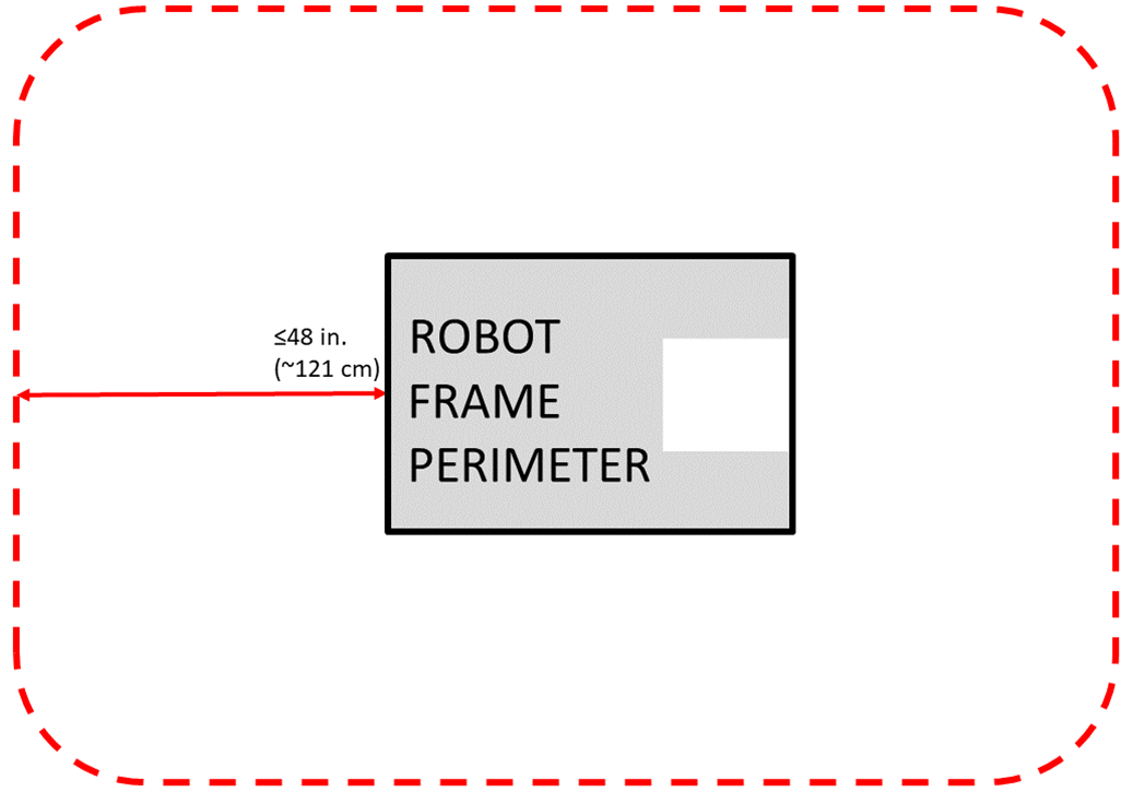
R104 Starting Configuration – max size.
A
Be sure to consider the size of the
Note that rules contained in Section 9.4
R105 Robot extension limit.
Teams should expect to have to demonstrate a
See Section 7 Game Rules:
9.2 ROBOT Safety & Damage Prevention
R201 *No digging into carpet.
Traction devices must not have surface features that could damage the
R202 *No exposed sharp edges.
Protrusions from the
R203 *General safety.
Examples of items that will violate this rule include (but are not limited to):
- a. shields, curtains, or any other devices or materials designed or used to obstruct or limit the vision of any members and/or interfere with their ability to safelyDRIVE TEAMtheircontrol,ROBOT
- b. speakers, sirens, air horns, or other audio devices that generate sound at a sufficient to be a distraction,level
- c. any devices or decorations specifically intended to jam or interfere with the remote sensing capabilities of another , including vision systems, acoustic range finders, sonars, infrared proximity detectors, etc. (e.g. including imagery on yourROBOTthat, to a reasonably astute observer, mimics the retro-reflective features of vision targets described in Section 5.9 Vision Targets),ROBOT
- d. exposed lasers other than Class I,
- e. flammable gasses,
- f. any device intended to produce flames or pyrotechnics,
- g. hydraulic fluids or hydraulic items,
- h. switches or contacts containing liquid mercury,
- i. circuitry used to create voltages in excess of 24 Volts,
- j. any ballast not secured sufficiently, including loose ballast e.g. sand, ball bearings, etc., such that it may become loose during a ,MATCH
- k. exposed, untreated hazardous materials (e.g. lead weights) used on the . These materials may be permitted if painted, encapsulated, or otherwise sealed to prevent contact. These materials may not be machined in any way at an event.ROBOT
- l. tire sealant, and
- m. high intensity light sources used on the (e.g. super bright LED sources marketed as ‘military grade’ or ‘self-defense’) may only be illuminated for a brief time while targeting and may need to be shrouded to prevent any exposure to participants. Complaints about the use of such light sources will be followed by re-inspection and possible disablement of the device.ROBOT
R204 *GAME PIECES stay with the Field.
Teams are encouraged to consider H312 when developing their
R205 *Don’t contaminate the Field.
Lubricants may be used only to reduce friction within the
R206 *Don’t damage GAME PIECES.
9.3 Budget Constraints & Fabrication Schedule
R301 *Individual item cost limit.
No individual, non-KOP item or software shall have a Fair Market Value (FMV) that exceeds $600 USD. The total cost of
Teams should be ready to show
The Analog Devices IMU
The FMV of a
The FMV of
The FMV of FABRICATED parts is the value of the material and/or labor, except for labor provided by team members (including sponsor employees who are members of the team), members of other teams, and/or event provided machine shops. Material costs are accounted for as the cost of any purchasable quantity that can be used to make the individual part (i.e. the purchasable raw material is larger than the FABRICATED part).
Example 1: A team orders a custom bracket made by a company to the team's specification. The company’s material cost and normally charged labor rate apply.
Example 2: A team receives a donated sensor. The company would normally sell this item for $450 USD, which is therefore its FMV.
Example 3: A team purchases titanium tube stock for $400 USD and has it machined by a local machine shop. The machine shop is not considered a team sponsor but donates 2 hours of expended labor anyway. The team must include the estimated normal cost of the labor as if it were paid to the machine shop and add it to the $400 USD.
Example 4: A team purchases titanium tube stock for $400 USD and has it machined by a local machine shop that is a recognized sponsor of the team. If the machinists are considered members of the team, their labor costs do not apply. The total applicable cost for the part would be $400 USD.
It is in the best interests of the teams and FIRST to form relationships with as many organizations as possible. Recognizing supporting companies as sponsors of, and members in, the team is encouraged, even if the involvement of the sponsor is solely through the donation of fabrication labor.
Example 5: A team purchases titanium tube stock for $400 USD and has it machined by another team. The total applicable cost for the part would be $400 USD.
Example 6: A team purchases a widget at a garage sale or online auction for $300, but it’s available for sale from a
If a
If the modules are designed to assemble into a single configuration, and the assembly is functional in only that configuration, then the total cost of the complete assembly including all modules must fit within the price constraints defined in this rule.
In summary, if a
Example 7:
Example 8:
Example 9:
R302 *Custom parts, generally from this year only.
- A. ,OPERATOR CONSOLE
- B. ,BUMPERS
- C. battery assemblies as described in R103-B,
- D. consisting of 1FABRICATED ITEMSelectrical device (e.g. a motor or motor controller) and attachedCOTSassociated with any of the following modifications:COMPONENTS
- a. wires modified to facilitate connection to a (including removal of existing connectors),ROBOT
- b. connectors and any materials to secure and insulate those connectors added (note: passive PCBs such as those used to adapt motor terminals to connectors are considered connectors),
- c. motor shafts modified and/or gears, pulleys, or sprockets added, and
- d. motors modified with a filtering capacitor as described in the blue box below R625.
- E. items, or functional equivalents, with any of the following modifications:COTS
- a. non-functional decoration or labeling,
- b. assembly of items per manufacturer specs, unless the result constitutes aCOTSas defined in I101, andMAJOR MECHANISM
- c. work that could be reasonably accomplished in fewer than 30 minutes with the use of handheld tools (e.g. drilling a small number of holes in a part).COTS
Please note that this means
Functionally equivalent items are items that closely resemble a
Parts with precision machined (mill, CNC, etc.) features may still meet part E.c of this rule if functionally equivalent features could reasonably be made within the restrictions specified.
Example 1: A team designs and builds a 2-speed shifting transmission during the fall as a training exercise. After Kickoff, they utilize all the design principles they learned in the fall to design their
Example 2: A team re-uses a CHARGED UP-legal motor from a previous
Example 3: A team re-uses a piece of aluminum tubing from a previous
R303 *Create new designs and software, unless they’re public.
Example 1: A team realizes that the transmission designed and built in the fall perfectly fits their need for a transmission to drive the
Example 2: A team developed an omni-directional drive system for the 2019 competition. In July 2019 they refined and improved the
Example 3: The same team decides to use LabVIEW as their software environment for CHARGED UP. Following Kickoff, they use the previously developed C++ code as a reference for the algorithms and calculations required to implement their omni-directional
Example 4: A different team develops a similar solution during the fall and plans to use the developed software on their competition
Example 5: A team develops a transmission prior to Kickoff. After completing the project, they publish the CAD files on a generally accessible public forum and make them available to all teams. Because they have made the design publicly available before Kickoff, they can use the design to create an identical transmission, fabricated after Kickoff, for use on their CHARGED UP
R304 *During an event, only work during pit hours.
During an event a team is attending (regardless of whether the team is physically at the event location), the team may neither work on nor practice with their
- A. exceptions listed in R302, other than R302-E-c,
- B. software development, and
- C. charging batteries.
For the purposes of this rule, official events begin as follows:
- Regionals, District Championships, and FIRST Championship: at the start of the first designated load-in period, according to the Public Schedule. If the Public Schedule is not available or there is no designated load-in period, the events begin at 4pm on the day prior to pits opening.
- District Events: when pits open Examples of activity prohibited by this rule include:
- a. working on the at the team’s shop after load-in for the event has begun,ROBOT
- b. working on parts at night at the team’s hotel, andROBOT
- c. running a 3D printer or other automated manufacturing process overnight producing parts. Note that E108 and E401 impose additional restrictions on work done on theROBOTorROBOTmaterials while attending an event.ROBOT
This rule is intended to increase equity between teams with significant travel to an event and those nearby (close teams would otherwise have an advantage by being able to work on their
9.4 BUMPER Rules
A
- minimize variety of so teams can expect consistency,BUMPERS
- minimize the amount of design challenge in creating ,BUMPERS
- minimize cost of materials, andBUMPER
- maximize use of relatively ubiquitous materials.
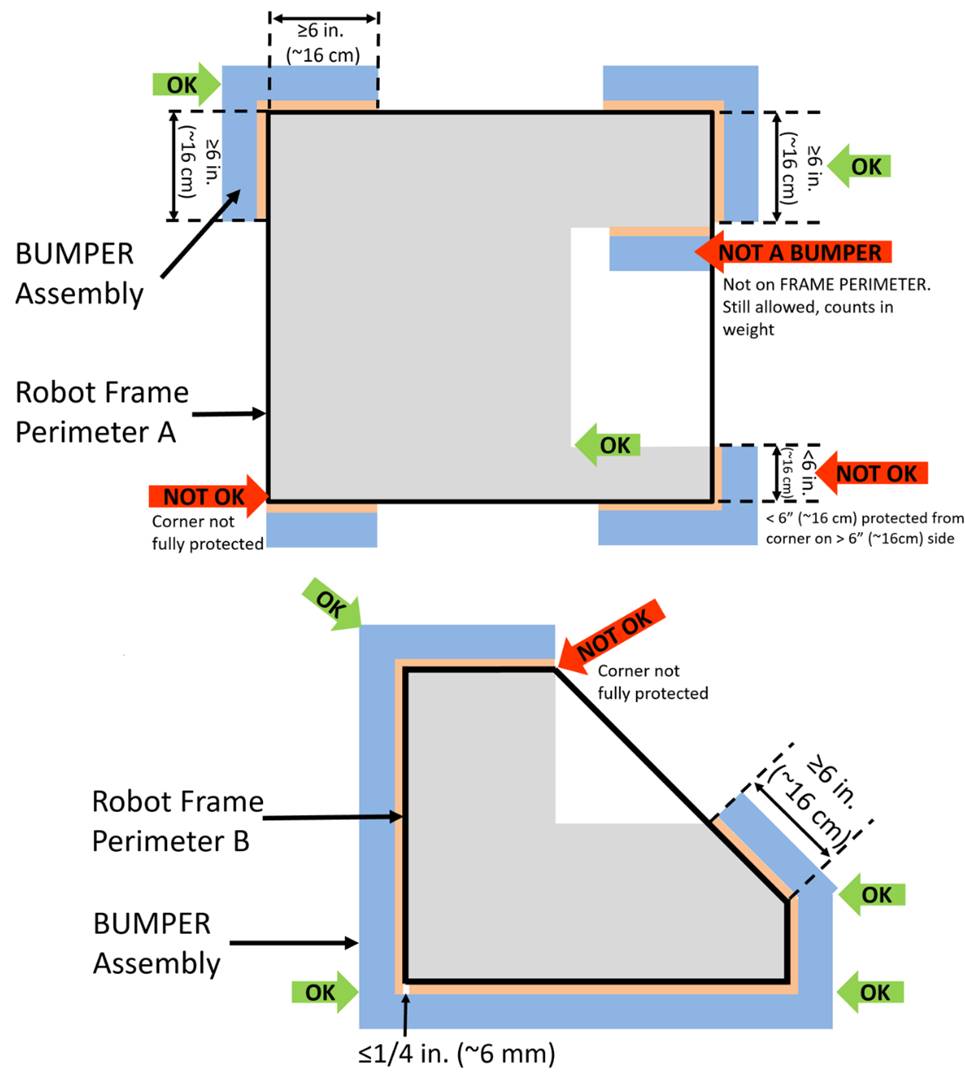
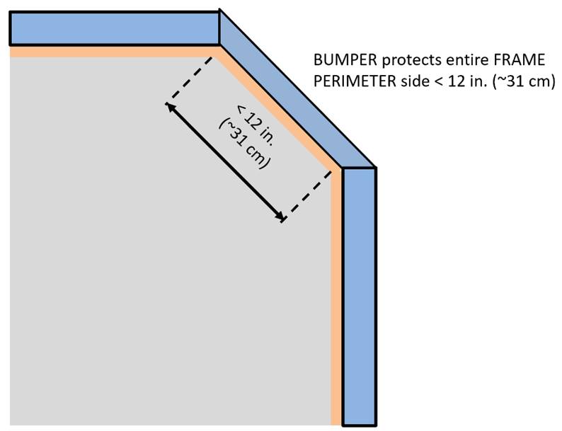
R401 *Bumpers should protect all corners.
The dimension defined in this rule is measured along the
R402 *Bumpers must stay low.
This measurement is intended to be made as if the
Example 1: A
Example 2: A
R404 *Bumpers must come off.
As a guideline,
R405 *Bumpers indicate your alliance.
Each
- A. those required per R406,
- B. hook-and-loop tape, snap fasteners, or functional equivalents backed by the hard parts of the ,BUMPER
- C. solid white FIRST logos between 4¾ in. (~12 cm) and 5¼ in. wide (~13 cm) (i.e. comparable to those available in the CHARGED UP Virtual Kit), and
- D. narrow areas of underlying fabric exposed at seams, corners, or folds.
The
R406 *Team number on bumpers.
Team numbers must be displayed and positioned on the
- A. consist of only white Arabic numerals at least 4 in. (~11 cm) high, at least ½ in. (~13 mm) in stroke width,
The ½ in. (~13 mm) stroke width requirement applies to the majority of the stroke. Font elements less than ½ in. (~13 mm) such as serifs, rounded edges, small hairlines or gaps, etc. are permitted as long as the majority of the stroke meets the sizing requirement and the numbers are unambiguous.
- B. must not wrap around sharp corners (less than 160°) of the , andFRAME PERIMETER
- C. may not substitute logos or icons for numerals.
There is no prohibition against splitting team numbers onto different sections of
This marking is intended to display the team number only, not to intentionally change the surface characteristics of the
R407 *Bumper weight limit.
Each set of
If a multi-part attachment system is utilized (e.g. interlocking brackets on the
R408 *Bumper construction.
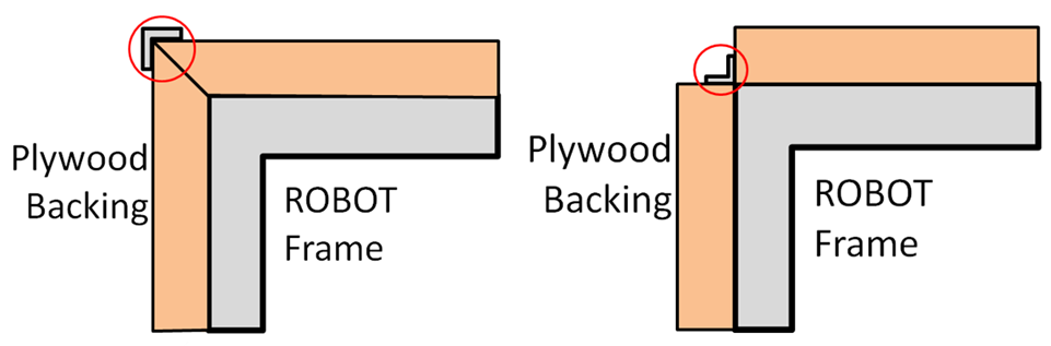
- A. be backed by ¾ in. thick (nominal, ~19mm) by 5 in. ± ½ in. (~127 mm ± 12.7 mm) tall plywood, Oriented Strand Board (OSB) or solid wood (with the exception of balsa). Small clearance pockets to accommodate minor protrusions permitted per R101 and/or holes needed to access or recess mounting hardware in the wood backing are permitted, as long as they do not significantly affect the structural integrity of the .BUMPER
¾ in. plywood and OSB refer to items sold by
as that material and thickness, teams may not fabricate their own plywood or OSB. Other engineered woods such as Fiberboard or Particle Board are not likely to survive the rigors of FIRST Robotics Competition gameplay and thus not permitted per A.VENDORSNote: ¾ in. plywood is often marked according to the actual dimension (²³⁄₃₂”) not the nominal size. Plywood sold as ²³⁄₃₂” meets the requirements of A.
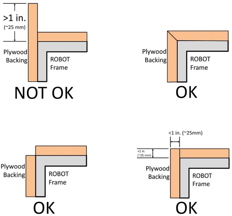
- B. hard parts allowed per A, E, F, and G must not extend more than 1 in. (~25 mm) beyond theBUMPER(measured as shown in Figure 9‑5).FRAME PERIMETER
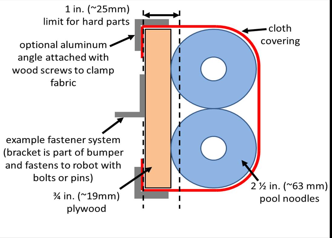
- C. use a stacked pair of 2½ in. (~63 mm) round, petal, or hex “pool noodles” (solid or hollow) as the cushion material (see Figure 9‑7). All pool noodles used in aBUMPERset (e.g. red set ofBUMPER) may not be modified (with the exception of cutting to length or cutting to facilitate mating pool noodles at the corners as required by R409) or deformed and must be the same diameter, cross section, and density (e.g. all round hollow or all hex solid). Per R409 cushion material may extend beyond the end of the plywood in order to fill a corner (see Figure 9‑8). To assist in applying the fabric covering, soft fasteners may be used to attach the pool noodles to the wood backing, so long as the cross section in Figure 9‑7 is not significantly altered (e.g. tape compressing the pool noodles).BUMPERS
“2½ in. (~63 mm) pool noodles” are pool noodles either sold as 2½ in. (~63 mm) diameter or that measure between 2¼ in. (~57 mm) pool noodles and 2¾ in. (~70 mm) diameter.
All pool noodles used on a
must be the same in order to maintain the desired interaction betweenROBOTin the cases of BUMPER-to-BUMPER contact.ROBOTScontaining pool noodles of vastly different construction may cause a “ramp” effect when interacting with otherBUMPERS.BUMPERSMinor noodle compression as a result of smoothing
fabric or rounding aBUMPERcorner is not considered deformed. Any compression beyond that, e.g. for the purposes of flattening the pool noodle, is deformation and a violation of C.FRAME PERIMETER - D. be covered with a rugged, smooth cloth with no additional coating applied by the team except for markings permitted per R405 (multiple layers of cloth and seams are permitted if needed to accommodate R405 and/or R406, provided the cross section in Figure 9‑7 is not significantly altered).BUMPER
Silk and bedding are not considered rugged cloths, however 1000D Cordura is. Tape (e.g. gaffer’s tape) matching the
color is allowed to patch small holes on a temporary basis.BUMPERIt is expected that there may be multiple layers of cloth as fabric is folded to accommodate the corners and seams of
.BUMPERS
The cloth must completely enclose all exterior surfaces of the wood and pool noodle material when the
- E. optionally use metal angle, as shown in Figure 9‑7 or other fasteners (e.g. staples, screws, adhesives, etc.) to clamp cloth.
- F. optionally use metal brackets (i.e. angle or sheet metal) or other fasteners (e.g. staples, screws, adhesives, etc.) to attach segments to each other (see Figure 9‑6).BUMPER
- G. must attach to the of theFRAME PERIMETERwith a rigid fastening system to form a tight, robust connection to the main structure/frame (e.g. not attached with hook-and-loop tape, tape, or cable ties). The attachment system must be designed to withstand vigorous game play. All removable fasteners (e.g. bolts, lockingROBOT, pip-pins, etc.) will be considered part of thepins.BUMPERS
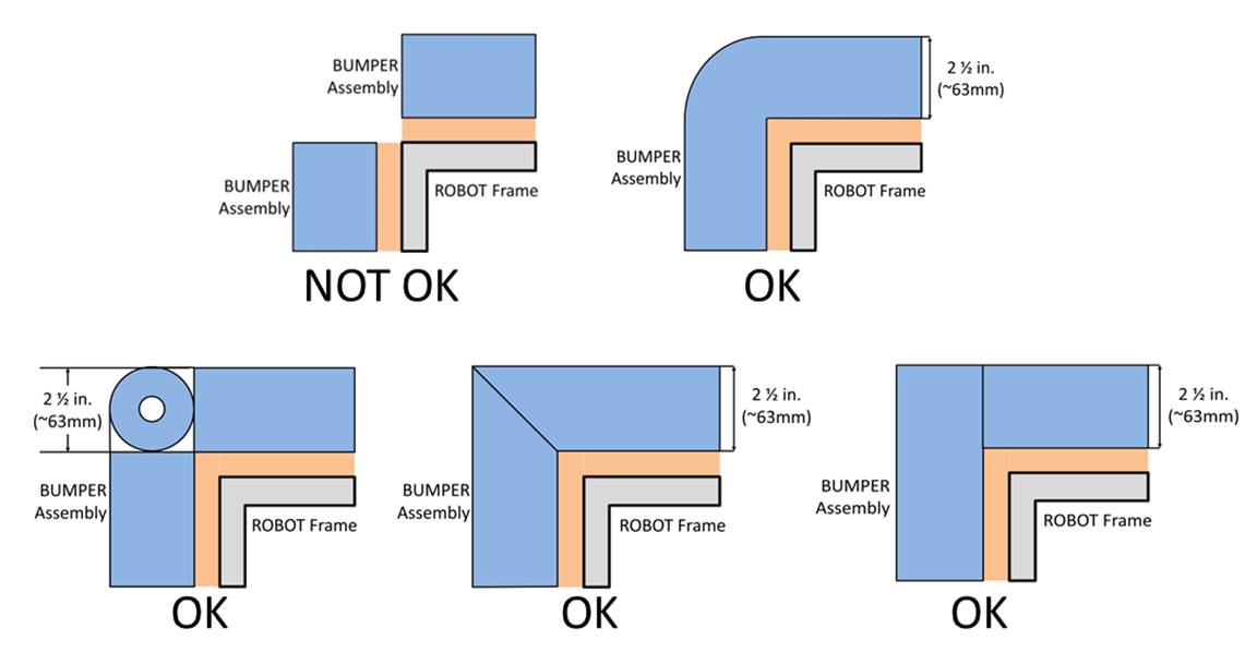
R409 *Fill Bumper corners.
Corner joints between
R410 *Bumpers must be supported.
- A. must not be greater than ¼ in. (~6 mm) deep or
- B. not more than 8 in. (~20 cm) wide
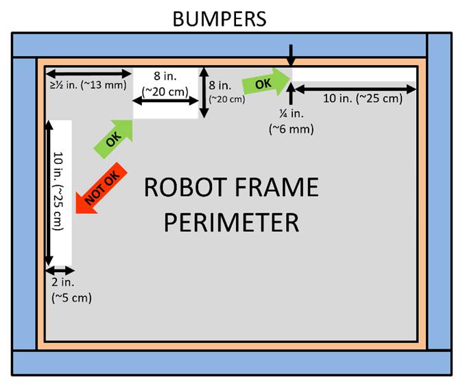
The intent of this rule is to make sure the
9.5 Motors & Actuators
R501 *Allowable motors.
The only motors and actuators permitted include the following (in any quantity):
| Motor Name | Part Numbers Available | Part Numbers Available |
|---|---|---|
| AndyMark 9015 | am-0912 | AndyMark 9015 |
| AndyMark NeveRest | am-3104 | |
| AndyMark PG | am-2161 (alt. PN am-2765) | am-2194 (alt. PN am-2766) |
| AndyMark RedLine Motor | am-3775 | am-3775a |
| AndyMark Snow Blower Motor | am-2235 | am-2235a |
| Banebots | am-3830 M7-RS775-18 RS775WC-8514 | M5 – RS550-12 RS550VC-7527 RS550 |
| CIM | FR801-001 M4-R0062-12 AM802-001A 217-2000 PM25R-44F-1005 | PM25R-45F-1004 PM25R-45F-1003 PMR25R-45F-1003 PMR25R-44F-1005 am-0255 |
| CTR Electronics/VEX Robotics Falcon 500 | 217-6515 am-6515 | 19-708850 am-6515_Short |
| Current/former KOP | Denso AE235100-0160 Denso 5-163800-RC1 Denso 262100-3030 | Denso 262100-3040 Bosch 6 004 RA3 194-06 Johnson Electric JE-PLG-149 Johnson Electric JE-PLG-410 |
| Nidec Dynamo BLDC Motor | am-3740 | DM3012-1063 |
| Playing with Fusion Venom | BDC-10001 | |
| REV Robotics HD Hex | REV-41-1291 | |
| REV Robotics NEO Brushless | REV-21-1650 (v1.0 or v1.1) | am-4258 am-4258a |
| REV Robotics NEO 550 | REV-21-1651 | am-4259 |
| VEX BAG | 217-3351 | |
| VEX Mini-CIM | 217-3371 | |
| West Coast Products RS775 Pro | 217-4347 | |
| Electrical solenoid actuators, no greater than 1 in. (nominal) stroke and rated electrical input power no greater than 10 watts (W) continuous | Electrical solenoid actuators, no greater than 1 in. (nominal) stroke and rated electrical input power no greater than 10 watts (W) continuous | Electrical solenoid actuators, no greater than 1 in. (nominal) stroke and rated electrical input power no greater than 10 watts (W) continuous |
| Fans, no greater than 120mm (nominal) size and rated electrical input power no greater than 10 watts (W) continuous | Fans, no greater than 120mm (nominal) size and rated electrical input power no greater than 10 watts (W) continuous | Fans, no greater than 120mm (nominal) size and rated electrical input power no greater than 10 watts (W) continuous |
| Hard drive motors part of a legal COTS | Hard drive motors part of a legal COTS | Hard drive motors part of a legal COTS |
| Factory installed vibration and autofocus motors resident in COTS | Factory installed vibration and autofocus motors resident in COTS | Factory installed vibration and autofocus motors resident in COTS |
| PWM COTS | PWM COTS | PWM COTS |
| Motors integral to a COTS | Motors integral to a COTS | Motors integral to a COTS |
| 1 compressor compliant with R806 and used to compress air for the ROBOT | 1 compressor compliant with R806 and used to compress air for the ROBOT | 1 compressor compliant with R806 and used to compress air for the ROBOT |
| Linear actuators rated for 12V and wired downstream of a breaker 20A or less | Linear actuators rated for 12V and wired downstream of a breaker 20A or less | Linear actuators rated for 12V and wired downstream of a breaker 20A or less |
For servos, note that the roboRIO is limited to a max current output of 2.2A on the 6V rail (12.4W of electrical input power). Teams should make sure that their total servo power usage remains below this limit at all times.
Given the extensive amount of motors allowed on the
AndyMark PG Gearmotors are sold with labeling based on the entire assembly. Assemblies labeled am-3651 through am-3656 contain legal motors specified in the table above. These motors may be used with or without the provided gearbox.
R502 *Don’t modify motors (mostly).
The integral mechanical and electrical system of any motor must not be modified. Motors, servos, and electric solenoids used on the
- A. The mounting brackets and/or output shaft/interface may be modified to facilitate the physical connection of the motor to the and actuated part.ROBOT
- B. The electrical leads may be trimmed to length as necessary and connectors or splices to additional wiring may be added.
- C. The locking on the window motors (P/N 262100-3030 and 262100-3040) may be removed.pins
- D. The connector housings on automotive motors listed in Table 9‑1 may be modified to facilitate lead connections.KOP
- E. Servos may be modified as specified by the manufacturer (e.g. re-programming or modification for rotation).continuous
- F. The wiring harness of the Nidec Dynamo BLDC Motor may be modified as documented by FIRST in Nidec Dynamo BLDC Motor with Controller.
- G. Minimal labeling may be applied to indicate device purpose, connectivity, functional performance, etc.
- H. Any number of #10-32 plug screws may be removed from the Falcon 500.
- I. Insulation may be applied to electrical terminals.
- J. Repairs, provided the performance and specifications are unchanged.
- K. Maintenance recommended by the manufacturer.
The intent of this rule is to allow teams to modify mounting tabs and the like, not to gain a weight reduction by potentially compromising the structural integrity of any motor.
R503 *Power (most) actuators off of approved devices.
With the exception of servos, fans, or motors integral to sensors of
- A. motor controllers,
- a. DMC 60/DMC 60c Motor Controller (P/N 410-334-1, 410-334-2),
- b. Jaguar Motor Controller (P/N MDL-BDC, MDL-BDC24, and 217-3367) connected to PWM only,
- c. Nidec Dynamo, BLDC Motor with Controller to integral actuator only (P/N 840205-000, am-3740)control
- d. SD540 Motor Controller (P/N SD540x1, SD540x2, SD540x4, SD540Bx1, SD540Bx2, SD540Bx4, SD540C),
- e. Spark Motor Controller (P/N REV-11-1200, am-4260),
- f. Spark MAX Motor Controller (P/N REV-11-2158, am-4261),
- g. Talon FX Motor Controller (P/N 217-6515, 19-708850, am-6515, am-6515_Short) for controlling integral Falcon 500 only,
- h. Talon Motor Controller (P/N CTRE_Talon, CTRE_Talon_SR, and am-2195),
- i. Talon SRX Motor Controller (P/N 217-8080, am-2854, 14-838288),
- j. Venom Motor with Controller (P/N BDC-10001) for controlling integral motor only,
- k. Victor 884 Motor Controller (P/N VICTOR-884-12/12),
- l. Victor 888 Motor Controller (P/N 217-2769),
- m. Victor SP Motor Controller (P/N 217-9090, am-2855, 14-868380), and
- n. Victor SPX Motor Controller (P/N 217-9191, 17-868388, am-3748),
- B. relay modules,
- a. Spike H-Bridge Relay (P/N 217-0220 and SPIKE-RELAY-H),
- b. Automation Direct Relay (P/N AD-SSR6M12-DC-200D, AD-SSRM6M25-DC-200D, AD-SSR6M40-DC-200D), and
- c. Power Distribution Hub () switched channel (P/N REV-11-1850) for controlling non-actuatorPDHonly,CUSTOM CIRCUITS
- C. pneumatics controllers,
- a. Pneumatics Module (P/N am-2858, 217-4243) andControl
- b. Pneumatic Hub (P/N REV-11-1852).
Note: The Automation Direct Relays are single directional. Per R504 they may not be wired together in an attempt to provide bi-directional
R504 *Don’t overload controllers.
Each power regulating device may
| Electrical Load | Motor Controller | Relay Module | Pneumatics Controller |
|---|---|---|---|
| AndyMark RedLine Motor Banebots CIM REV Robotics NEO Brushless REV Robotics NEO 550 VEX Mini-CIM WCP RS775 Pro | Yes | No | No |
| AndyMark 9015 VEXpro BAG | Yes (up to 2 per controller) | No | No |
| AndyMark PG KOP | Yes (up to 2 per controller) | Yes | No |
| Linear Actuator | Yes (20A breaker max) | Yes (20A breaker max) | No |
| CTR Electronics/VEX Falcon 500 Nidec Dynamo BLDC Motor w/ Controller Playing With Fusion Venom | Yes (integrated controller only) | No | No |
| Compressor | No | Yes | Yes |
| Pneumatic Solenoid Valves | No | Yes (multiple) | Yes (1 per channel) |
| Electric Solenoids | Yes (multiple) | Yes (multiple) | Yes (1 per channel) |
CUSTOM CIRCUITS | Yes (multiple) | Yes (multiple) | Yes (multiple) |
R505 *Control servos safely.
Servos must be connected to, and only to, 1 of the following:
- A. PWM ports on the roboRIO,
- B. PWM ports on a WCP Spartan Sensor Board (P/N WCP-0045), or
- C. REV Robotics Servo Power Module (P/N REV-11-1144).
9.6 Power Distribution
In order to maintain safety, the rules in this section apply at all times while at the event, not just while the
R601 *Battery limit – everyone has the same power.
The only legal source of electrical energy for the
- A. Nominal voltage: 12V
- B. Nominal capacity at 20-hour discharge rate: minimum 17Ah, maximum 18.2Ah
- C. Shape: Rectangular
- D. Nominal Dimensions: 7.1 in. x 3 in. x 6.6 in., +/- .1 in. for each dimension (~ 180 mm x 76mm x 168 mm, +/- 2.5 mm for each dimension)
- E. Nominal weight: 11lbs. to 14.5 lbs. (~5 kg. to 6.5 kg.)
- F. Terminals: Nut and bolt style
Examples of batteries which meet these criteria include:
- a. Enersys (P/N NP18-12, NP18-12B, NP18-12BFR),
- b. MK Battery (P/N ES17-12),
- c. Battery Mart (P/N SLA-12V18),
- d. Sigma (P/N SP12-18),
- e. Universal Battery (P/N UB12180),
- f. Power Patrol (P/N SLA1116),
- g. Werker Battery (P/N WKA12-18NB),
- h. Power Sonic (P/N PS-12180NB),
- i. Yuasa (P/N NP18-12B),
- j. Panasonic (P/N LC-RD-1217),
- k. Interstate Batteries (P/N BSL1116), and
- l. Duracell Ultra Battery (P/N DURA12-18NB). Teams should be aware that they may be asked to provide documentation of the specifications of any battery not listed above.
Batteries should be charged in accordance with manufacturer’s specification. (Please see the FIRST Safety Manual for additional information.)
R602 *Other batteries for cameras or computers only.
- A. securely fastened to the ,ROBOT
- B. connected only using unmodified cables, andCOTS
- C. charged according to manufacturer recommendations.
A
R603 *Charge batteries with safe connectors.
Any battery charger used to charge a
R604 *Charge batteries at a safe rate.
Any battery charger used to charge a
R605 *Batteries are not ballast.
No batteries other than those allowed per R601 and R602 are allowed on the
For example, teams may not use additional batteries as extra weight on their
R606 *Secure the battery.
The
R607 *Insulate battery connections.
Each electrical terminal on the
R608 *Limit non-battery energy.
Non-electrical sources of energy used by the
- A. compressed air stored in the pneumatic system that has been charged in compliance with R806 and R807,
- B. a change in the altitude of the center of gravity,ROBOT
- C. storage achieved by deformation of parts,ROBOT
- D. closed-loop pneumatic (gas) shocks, orCOTS
- E. air-filled (pneumatic) wheels.
R609 *Connect main power safely.
The 1
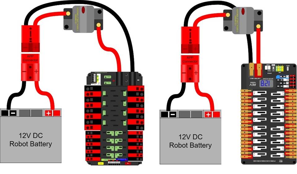
“SB type” refers to SB type only (e.g. SB-50, SB-120, etc.), not SBS or any other part type beginning with SB. All batteries supplied by FIRST (such as Spare Parts and international batteries) will have a red or pink SB50 connector installed which may not be removed.
The pink connectors included in the CHARGED UP
R610 *1 breaker per circuit.
All circuits, with the exceptions of those listed in R615 and R617, must connect to, and have power sourced solely by, a single protected 12VDC WAGO connector pair (i.e. the load terminals, as shown in Figure 9‑10) of the
R611 *The Robot frame is not a wire.
All wiring and electrical devices shall be electrically isolated from the
Compliance with this rule is checked by observing a >120Ω resistance between either the (+) or (-) post within the APP connector that is attached to the
All legal motor controllers with metal cases are electrically isolated. They may be mounted directly to
Note that some cameras, decorative lights, and sensors (e.g. some encoders, some IR sensors, etc.) have grounded enclosures or are manufactured with conductive plastics. These devices must be electrically isolated from the
R612 *Must be able to turn robot on and off safely.
The 120A circuit breaker must be quickly and safely accessible from the exterior of the
Examples considered not “quickly and safely accessible” include breakers covered by an access panel or door, or mounted on, underneath or immediately adjacent to moving
It is strongly recommended that the 120A circuit breaker location be clearly and obviously labeled so it can be easily found by
R613 *Electrical system must be inspectable.
The
“Visible for inspection” does not require that the items be visible when the
R614 *No high voltage allowed.
Any active electrical item that is not an actuator (specified in R501) or core
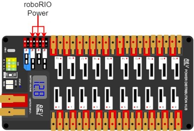
R615 *Power roboRIO as specified.
The roboRIO power input must be connected to either:
- A. the dedicated supply terminals on the shown in Figure 9‑11 orPDP
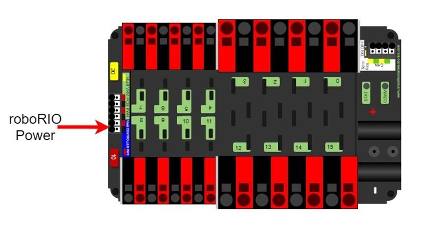
- B. the terminals of 1 of the non-switchable fused channels on the (20,21,22) with a 10A fuse installed in the associated fuse holder. No other electrical load shall be connected to that channel.PDH
R616 *Power radio as specified – Part 1.
The wireless bridge (radio) power must be supplied by either:
- A. the 12V 2A output of a CTR Electronics Voltage Regulator Module () (P/N am-2857, 217-4245), as shown in Figure 9‑13, and must be the only load connected to those terminals orVRM
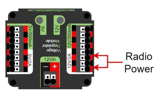
- B. using an Ethernet cable between a REV Radio Power Module () (P/N REV-11-1856) and the “18-24v POE” Ethernet port on the wireless bridge.RPM
Note that this prohibits using any other active POE injector device to power the radio but does not prohibit using any
to inject thePASSIVE CONDUCTORSpower into an Ethernet cable plugged into the radio port labeled “18-24v POE.”VRM
R617 *Power radio as specified – Part 2.
The device supplying power to the wireless bridge per R616 must be connected to either:
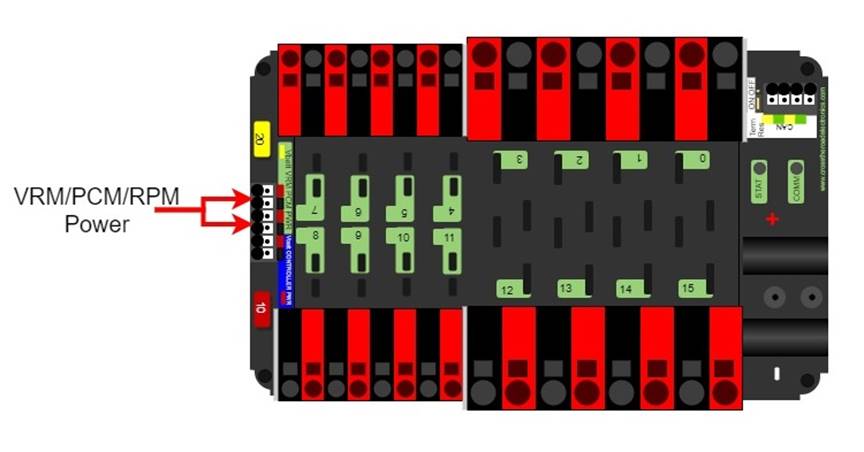
- A. the designated supply terminals at the end of the , as shown in Figure 9‑14. With the exception of a single CTR Electronics PneumaticsPDPModule (Control, P/N am-2858) or REV Robotics Pneumatic Hub (PCM, P/N REV-11-1852), no other electrical load shall be connected to thesePHterminals.PDP
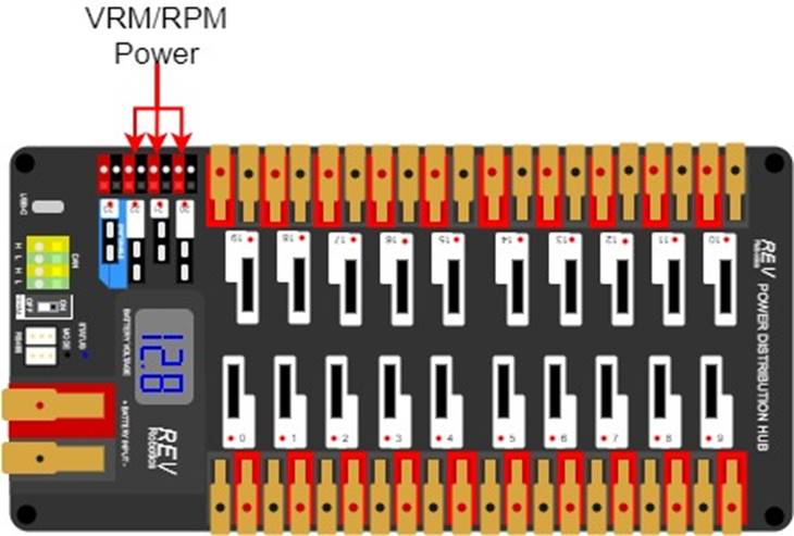
- B. the terminals of 1 of the non-switchable fused channels on the (20,21,22) with a 10A fuse installed in the associated fuse holder. No other electrical load shall be connected to that channel.PDH
Please reference How to Wire an FRC
R618 *Use PDP/PDH terminals as designed.
Only 1 wire shall be connected to each terminal on the
If multi-point distribution of circuit power is needed (e.g. to provide power to multiple
R619 *Only use specified circuit breakers in PDP/PDH.
The only circuit breakers permitted for use in the
- A. Snap Action VB3-A Series or AT2-A, terminal style F57, 40A rating or lower,
- B. Snap Action MX5-A or MX5-L Series, 40A rating or lower, and
- C. REV Robotics ATO auto-resetting breakers 40A rating or lower.
R620 *Only use specified fuses in PDP/PDH.
The only fuses permitted for use in the
- A. for the , values matching the value printed on the device’s corresponding fuse holder andPDP
- B. for the , 15A or lower with the exception of a single 20A fuse for powering aPDHorPCM.PH
Note that these fuses must be pressed very firmly to seat properly. Improper seating can cause a device to reboot upon impact.
R621 *Protect circuits with appropriate circuit breakers.
Each branch circuit must be protected by 1 and only 1 circuit breaker or fuse on the
| Branch Circuit | Circuit Breaker Value | Quantity Allowed Per Breaker |
|---|---|---|
| Motor Controller | Up to 40A | 1 |
CUSTOM CIRCUIT | Up to 40A | No limit |
| Automation Direct Relay 40A (6M40) | Up to 40A | 1 |
| Fans permitted per R501 and not already part of COTS | Up to 20A | No limit |
| Spike Relay Module | Up to 20A | 1 |
| Automation Direct Relay 25A (6M25) | Up to 20A | 1 |
PCM PH | Up to 20A | 1 |
| Additional VRM PCM PH | Up to 20A | 3 total |
| Automation Direct Relay 12A (6M12) | Up to 10A | 1 |
This rule does not prohibit the use of smaller value breakers in the
R622 *Use appropriately sized wire.
All circuits shall be wired with appropriately sized insulated copper wire (
| Application | Minimum Wire Size |
|---|---|
| 31 – 40A breaker protected circuit | 12 AWG (13 SWG or 4 mm2) |
| 21 – 30A breaker protected circuit | 14 AWG (16 SWG or 2.5 mm2) |
| 6 – 20A breaker protected circuit | 18 AWG (19 SWG or 1 mm2) |
| 11-20A fuse protected circuit | |
| Between the PDP VRM RPM PCM PH | |
| Compressor outputs from the PCM PH | |
| Between the PDH PCM PH | |
| Between the PDP PDH | 22 AWG (22 SWG or 0.5 mm2) |
| Between the PDH VRM RPM | |
| ≤5A breaker protected circuit | |
| ≤10A fuse protected circuit | |
VRM | 24 AWG (24 SWG or .25 mm2) |
| roboRIO PWM port outputs | 26 AWG (27 SWG or 0.14 mm2) |
SIGNAL LEVEL continuous PCM PH VRM RPM | 28 AWG (29 SWG or .08 mm2) |
Wires that are recommended by the device manufacturer or originally attached to legal devices are considered part of the device and by default legal. Such wires are exempt from this rule.
In order to show compliance with these rules, teams should use wire with clearly labeled sizes if possible. If unlabeled wiring is used, teams should be prepared to demonstrate that the wire used meets the requirements of this rule (e.g. wire samples and evidence that they are the required size).
R623 *Use only appropriate connectors.
Branch circuits may include intermediate elements such as
Slip rings containing mercury are prohibited per R203.
R624 *Use specified wire colors (mostly).
All non-SIGNAL
- A. red, yellow, white, brown, or black-with-stripe on the positive (e.g. +24VDC, +12VDC, +5VDC, etc.) connections
- B. black or blue for the common or negative side (-) of the connections
Exceptions to this rule include:
- C. wires that are originally attached to legal devices and any extensions to these wires using the same color as the manufacturer
- D. Ethernet cable used in POE cables
R625 *Don’t modify critical power paths.
A noise filter may be wired across motor leads or PWM leads. Such filters will not be considered
Acceptable signal filters must be fully insulated and must be 1 of the following:
- a 1 microfarad (1 µF) or less, non-polarized, capacitor may be applied across the power leads of any motor on your (as close to the actual motor leads as reasonably possible) orROBOT
- a resistor may be used as a shunt load for the PWM signal feeding a servo.control
9.7 Control, Command & Signals System
R701 *Control the robot with a roboRIO.
There are no rules that prohibit co-processors, provided commands originate from the roboRIO to enable and disable all power regulating devices. This includes motor controllers legally wired to the CAN bus.
R702 *Communicate with the Robot with the specified radio.
1 OpenMesh wireless bridge (P/N: OM5P-AN or OM5P-AC), that has been configured with the appropriate encryption key for your team number at each event, is the only permitted device for communicating to and from the
R703 *Use specific Ethernet port for roboRIO.
The roboRIO Ethernet port must be connected to the wireless bridge port labeled “18-24 vPOE” (either directly, via a network switch, via an
Note: Placing a switch between the roboRIO and radio may impede the ability for
R704 *Only use allowed ports and bandwidth to communicate with the robot.
Communication between the
| Port | Designation | Bi-directional? |
|---|---|---|
| UDP/TCP 1180-1190 | Camera data from the roboRIO to dashboard software when the camera is connected the roboRIO via USB | Yes |
| TCP 1735 | SmartDashboard | Yes |
| UDP 1130 | Dashboard-to-ROBOT control | Yes |
| UDP 1140 | ROBOT-to-Dashboard status data | Yes |
| HTTP 80 | Camera connected via switch on the ROBOT | Yes |
| HTTP 443 | Camera connected via switch on the ROBOT | Yes |
| UDP/TCP 554 | Real-Time Streaming Protocol for h.264 camera streaming | Yes |
| UDP/TCP 1250 | CTRE Diagnostics Server | Yes |
| UDP/TCP 5800-5810 | Team use | Yes |
Teams may use these ports as they wish if they do not employ them as outlined above (i.e. TCP 1180 can be used to pass data back and forth between the
Note that the 4 Mbit limit will be strictly enforced by the wireless bridge.
The
While FIRST makes every effort to provide a wireless environment that allows teams access to a full 4 Mbits/second data rate (with about 100 Kbit used for
R705 *Configure devices for your team number.
The roboRIO,
R706 *Don’t bypass the arena network.
All signals must originate from the
R707 *No other wireless allowed.
No form of wireless communication shall be used to communicate to, from, or within the
Devices that employ signals in the visual spectrum (e.g. cameras) and non-RF sensors that don’t receive human-originated commands (e.g. “beam break” sensors or IR sensors on the
R708 *Wireless bridge must be visible.
The wireless bridge must be mounted on the
Teams are encouraged to mount the wireless bridge away from noise generating devices such as motors,
R709 *Robots must have a signal light.
Any
- A. mounted on the such that it is easily visible while standing 3 ft. (~ 100 cm) away from at least one side of theROBOT,ROBOT
- B. connected to the “” supply terminals on the roboRIO, andRSL
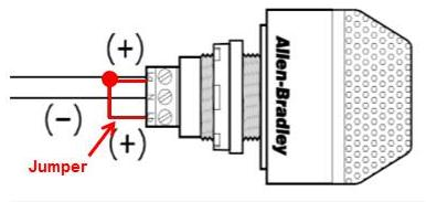
- C. if using the 855PB-B12ME522, wired for solid light operation, by placing a jumper between the “La” and “Lb” terminals on the light per Figure 9‑16.
Please see How to Wire an FRC
R710 *Only specified modifications to control system devices permitted.
The
Please note that the
- A. User programmable code in the roboRIO may be customized.
- B. Motor controllers may be calibrated as described in owner's manuals.
- C. Fans may be attached to motor controllers and may be powered from the power input terminals.
- D. If powering the compressor, the fuse on a Spike H-Bridge Relay may be replaced with a VB3A-20A Snap-Action circuit breaker.
- E. Wires, cables, and signal lines may be connected via the standard connection points provided on the devices.
- F. Fasteners (including adhesives) may be used to attach the device to the orOPERATOR CONSOLEor to secure cables to the device.ROBOT
- G. Thermal interface material may be used to improve heat conduction.
- H. Labeling may be applied to indicate device purpose, connectivity, functional performance, etc.
- I. Jumpers may be changed from their default location.
- J. Limit switch jumpers may be removed from a Jaguar motor controller and a custom limit switch circuit may be substituted.
- K. Device firmware may be updated with manufacturer supplied firmware.
- L. Integral wires on motor controllers may be cut, stripped, and/or connectorized.
- M. Devices may be repaired, provided the performance and specifications of the device after the repair are identical to those before the repair.
- N. The cover may be removed from the Talon SRX data port.
- O. Electrical tape may be applied to the aluminum plate inside the wireless bridge.
- P. The input terminal cover from the may be omitted (no other element may be installed using the threaded holes to install something in place of thePDPterminal cover).PDP
- Q. The roboRIO 2.0 SD card may be replaced with an SD card of any capacity.
- . adding insulating material to exposed conductors onR/PDHbreakers and fuses.PDP
- S. functional equivalents to SYSTEM power terminal blocks.CONTROL
Please note that while repairs are permitted, the allowance is independent of any manufacturer’s warranty. Teams make repairs at their own risk and should assume that any warranty or return options are forfeited. Be aware that diagnosing and repairing
For more information about modification O, please see this OM5P-AC Radio Modification article.
R711 *Don’t connect motor outputs to roboRIO.
Neither 12VDC power nor relay module or motor controller outputs shall be directly connected to the roboRIO, with the exception of the designated 12VDC input.
R712 *Control PWM controllers from the roboRIO.
Every relay module (per R503-B), servo controller, and PWM motor controller shall be connected to a corresponding port (relays to Relay ports, servo controllers and PWM controllers to PWM ports) on the roboRIO (either directly or through a WCP Spartan Sensor Board) or via a legal
R713 *Only approved MXP devices can control actuators.
If a motor is controlled via the
- A. directly to any PWM ,pins
- B. via a network of used to extend the PWMPASSIVE CONDUCTORS, orpins
- C. via 1 approved :ACTIVE DEVICE
- A. Kauai Labs navX MXP
- b. Kauai Labs navX2 MXP
- c. RCAL DaughterboardMXP
- d. REV Robotics RIOduino
- e. REV Robotics Digit Board
- f. West Coast Products Spartan Sensor Board
- g. Huskie Robotics HUSKIE 2.0 Board
A
An
The “network of
R714 *Control CAN motor controllers from the roboRIO.
Each CAN motor controller must be controlled with signal inputs sourced from the roboRIO and passed via either a PWM (wired per R713) or CAN bus (either directly or daisy-chained via another CAN bus device) signal, but both shall not be wired simultaneously on the same device.
As long as the CAN bus is wired legally so that the heartbeat from the roboRIO is maintained, all closed loop
“Wired directly” includes via any series of
R715 *Control PCM/PH(S) from roboRIO.
Each
R716 *Connect the PDP/PDH to the roboRIO CAN bus.
The
For documentation on how to wire the CAN bus connections see How to Wire an FRC
R717 *Don’t alter the CAN bus.
No device that interferes with, alters, or blocks communications among the roboRIO and the
Only 1 wire should be inserted into each Weidmuller CAN connector terminal. For documentation on how to wire the CAN bus connections see How to Wire an FRC
R718 *USB to CAN adapter permitted.
Additional CAN bus connections may be added to the roboRIO using the CTR Electronics CANivoreTM P/N 21-678682 USB-to-CAN adapter.
Any additional CAN bus added in this manner satisfies the requirements of R714 (i.e. you may connect motor controllers to this additional bus).
9.8 Pneumatic System
In order to maintain safety, the rules in this section apply at all times while at the event, not just while the
R801 *Only use explicitly permitted pneumatic parts.
To satisfy multiple constraints associated with safety, consistency, inspection, and constructive innovation, no pneumatic parts other than those explicitly permitted in this section shall be used on the
R802 *No custom pneumatics and meet minimum pressure ratings.
All pneumatic items must be
- A. rated by their manufacturers for pressure of at least 125psi (~862 kPa) or
- B. installed downstream of the primary relieving regulator (see R809), and rated for pressure of at least 70psi (~483 kPa)
Any pressure specification such as “working,” “operating,” “maximum,” etc. may be used to satisfy the requirements of this rule.
It is recommended that all pneumatic items be rated by their manufacturers for a working pressure of at least 60 psi (~414 kPa).
R803 *Don’t modify pneumatics.
All pneumatic
- A. tubing may be cut,
- B. wiring for pneumatic devices may be modified to interface with the system,control
- C. assembling and connecting pneumatic using the pre-existing threads, mounting brackets, quick-connect fittings, etc.,COMPONENTS
- D. removing the mounting from a pneumatic cylinder, provided the cylinder itself is not modified, andpin
- E. labeling applied to indicate device purpose, connectivity, functional performance, etc.
Do not, for example, paint, file, machine, or abrasively remove any part of a pneumatic
R804 *Only use specific pneumatic devices.
The only pneumatic system items permitted on
- A. pneumatic pressure vent plug valves functionally equivalent to those provided in the ,KOP
Examples of acceptable valves include Parker PV609-2 or MV709-2.
- B. pressure relief valves functionally equivalent to those provided in the ,KOP
Examples of acceptable valves include Norgren 16-004-011, 16-004-003 or McMaster-Carr 48435K714.
To be considered functionally equivalent the valve must be preset or adjustable to 125 psi (~862 kPA) and capable of relieving at least 1 scfm (~472 cm3/s).
- C. solenoid valves with a maximum ⅛ in. (nominal, ~3 mm) NPT, BSPP, or BSPT port diameter or integrated quick connect ¼ in. (nominal, ~6mm) outside diameter tubing connection,
- D. additional pneumatic tubing, with a maximum ¼ in. (nominal, ~6 mm) outside diameter,
- E. pressure transducers, pressure gauges, passive flow valves (specifically “needle valve”), manifolds, and connecting fittings (includingcontrolpneumatic U-tubes),COTS
- F. check and quick exhaust valves, provided that the requirements of R813 are still met.
- G. shutoff valves which relieve downstream pressure to atmosphere when closed (may also be known as 3-way or 3-way exhausting valves),
- H. pressure regulators with the maximum outlet pressure adjusted to no more than 60 psi (~413 kPa),
- I. pneumatic cylinders, pneumatic linear actuators, and rotary actuators,
- J. pneumatic storage tanks (with the exception of white Clippard tanks P/N AVT-PP-41),
- K. 1 compressor that is compliant with R806,
- L. debris or coalescing (water) filters, and
- M. Venturi valves (note: the high-pressure side of a Venturi valve is considered a pneumatic device and must follow all pneumatic rules. The vacuum side of a Venturi valve is exempt from the pneumatic rules per “a” in the blue box below).
The following devices are not considered pneumatic devices and are not subject to pneumatic rules (though they must satisfy all other rules):
- a. a device that creates a vacuum,
- b. closed-loop pneumatic (gas) shocks,COTS
- c. air-filled (pneumatic) wheels, and
- d. pneumatic devices not used as part of a pneumatic system (i.e. used in a way that does not allow them to contain pressurized air)
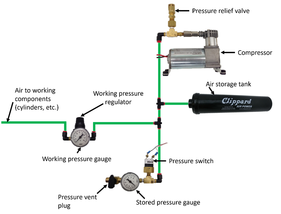
R805 *If using pneumatics, these parts are required.
If pneumatic
- A. 1 FIRST Robotics Competition legal compressor (per R806),
- B. a pressure relief valve (per R804-B) connected and calibrated (per R811),
- C. a Nason pressure switch (P/N SM-2B-115R/443) and/or REV Robotics Analog Pressure Sensor (P/N REV-11-1107) connected and wired per R812,
- D. at least 1 pressure vent plug plumbed (per R813),
- E. stored pressure gauge and working pressure gauge (per R810), and
- F. 1 primary working pressure regulator (per R808).
R806 *Compressed air from robot compressor only.
Throughout an event, compressed air on the
A
Note: Viair C-series compressors, which have a max working pressure of 120 PSI, are rated for intermittent pressures greater than 125 PSI and therefore meet the requirements of this rule.
R807 *Air storage pressure limit.
Stored air pressure on the
R808 *Working air pressure limit.
Working air pressure (air pressure used to actuate devices) on the
Examples of acceptable valves include Norgren regulator P/N R07-100-RNEA and Monnier P/N 101-3002-1.
R809 *Limited devices at high pressure.
Only the compressor, relief valve, pressure switch, pressure vent plug, pressure gauge, storage tanks, tubing, pressure transducers, filters, and connecting fittings may be in the high-pressure pneumatic circuit upstream from the regulator.
It is recommended that all
R810 *Pressure gauges must be visible.
Pressure gauges must be placed in easily visible locations upstream and downstream of the regulator to display the stored and working pressures, respectively. Pressure gauges must show pressure in psi or kPa.
R811 *Relief valve requirements.
The relief valve must be attached directly to the compressor or attached by legal hard fittings (e.g. brass, nylon, etc.) connected to the compressor output port.
Teams are required to check and/or adjust the relief valve to release air at 125 psi (~861 kPa). The valve may or may not have been calibrated prior to being supplied to teams.
Instructions for adjusting the pressure relief valve can be found in the Pneumatics Manual.
R812 *Pressure switch requirements.
The pressure switch must be connected to the high-pressure side of the pneumatic circuit (i.e. prior to the pressure regulator) to sense the stored pressure of the circuit.
It must be either:
- A. Nason P/N SM-2B-115R/443 (wired as described) and/or
The 2 wires from the pressure switch must be connected directly to the pressure switch input of the /PCMcontrolling the compressor or, if controlled using the roboRIO and a relay, to the roboRIO. If connected to the roboRIO, the roboRIO must be programmed to sense the state of the switch and operate the relay module that powers the compressor to prevent over-pressuring the system.PH
- B. REV Robotics P/N REV-11-1107 (wired as described)
The analog output of the sensor must be connected directly to analog input 0 of the (with firmware version 22.0.2 or newer) controlling the compressor.PH
The REV Robotics Analog Pressure Sensor may only be used with
R813 *Vent plug requirements.
Any pressure vent plug must be:
- A. connected to the pneumatic circuit such that, when manually operated, it will vent to the atmosphere to relieve all stored pressure in a reasonable amount of time and
- B. placed on the so that it is visible and easily accessible.ROBOT
R814 *Don’t connect solenoid outputs together.
The outputs from multiple solenoid valves must not be plumbed together.
9.9 OPERATOR CONSOLE
R901 *Use the specified Driver Station Software.
The
Teams are permitted to use a portable computing device of their choice (laptop computer, tablet, etc.) to host the
R902 *The operator console must have a visible display.
The
R903 *Connect FMS Ethernet directly to the operator console.
Devices hosting the
Teams are strongly encouraged to use pigtails on the Ethernet port used to connect to the
- A. be longer than 5 ft. (~152 cm),
- B. be deeper than 1 ft. 2 in. (~35 cm) (excluding any items that are held or worn by the during theDRIVERS),MATCH
- C. extend more than 6 ft. 6 in. (~198 cm) above the floor, or
- D. attach to the (except as permitted by G301).FIELD
There is a 4 ft. 6 in. (~137 cm) long by 2 in. (nominal) wide strip of hook-and-loop tape (“loop” side) along the center of the
Please note that while there is no hard weight limit,
R905 *Field wireless only.
Other than the system provided by the
Examples of prohibited wireless systems include, but are not limited to, active wireless network cards and Bluetooth devices. For the case of the FIRST Robotics Competition, a motion sensing input device (e.g. Microsoft Kinect) is not considered wireless communication and is allowed.
R906 *No unsafe operator consoles.
8 Game Rules: Humans
FIRST is committed to Equity, Diversity, and Inclusion and as such, FIRST makes reasonable accommodations for persons with disabilities that request accommodation. If a participant needs an accommodation for an event, please talk to a volunteer at the event or contact local leadership before the event so they can help ensure the accommodation is provided.
10 Inspection & Eligibility Rules
This section describes the rules governing MATCH participation. A team has participated in a MATCH if any member of their DRIVE TEAM is in the ALLIANCE AREA, with or without the ROBOT on the FIELD, at the start of the MATCH.