

5 ARENA
The
The
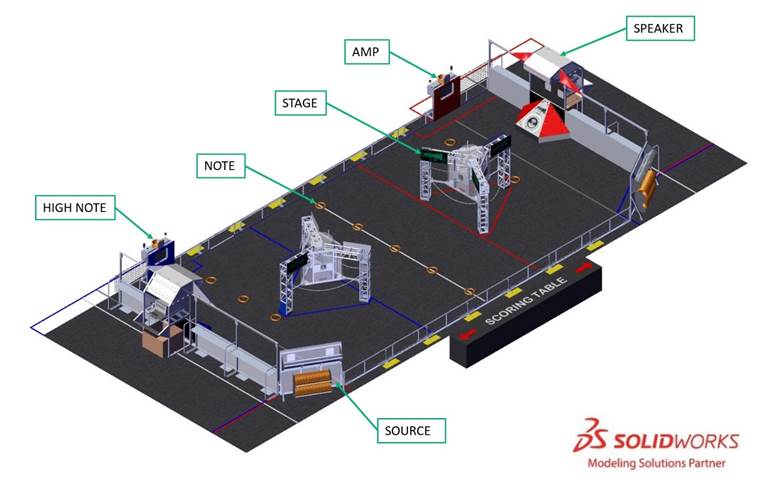
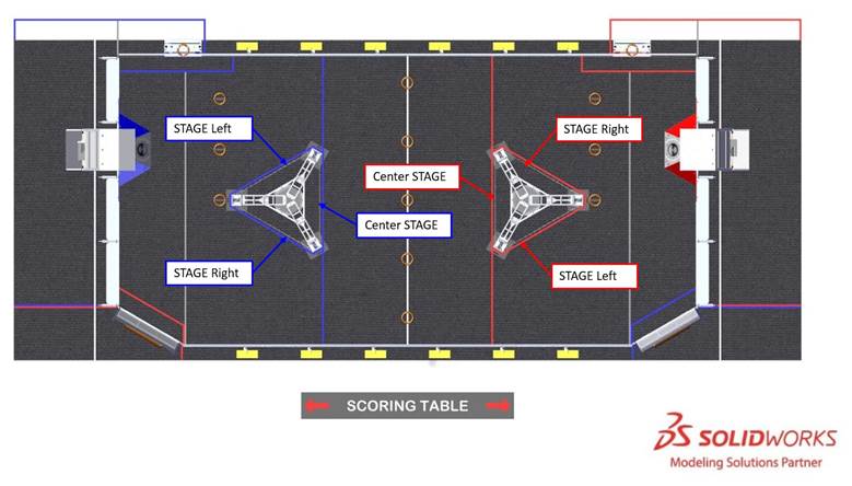
Illustrations included in this section are for a general visual understanding of the CRESCENDO
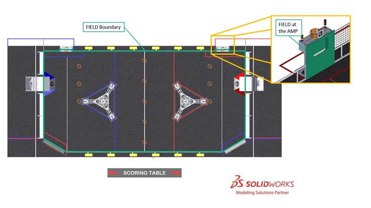
5.1 FIELD
Each
The
- 1 perAMP,ALLIANCE
- 1 perSPEAKER,ALLIANCE
- 1 perSOURCE, andALLIANCE
- 1 perSTAGE.ALLIANCE
The surface of the
Guardrails form the long edges of the
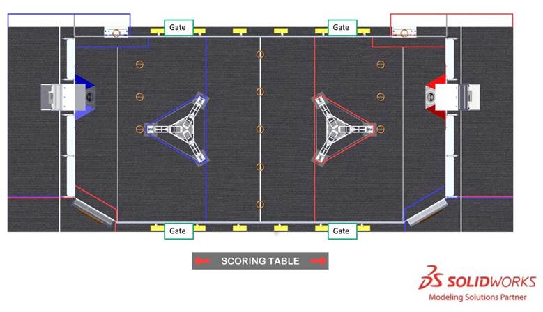
There are 2 versions of guardrails and
5.2 Areas, Zones, & Markings
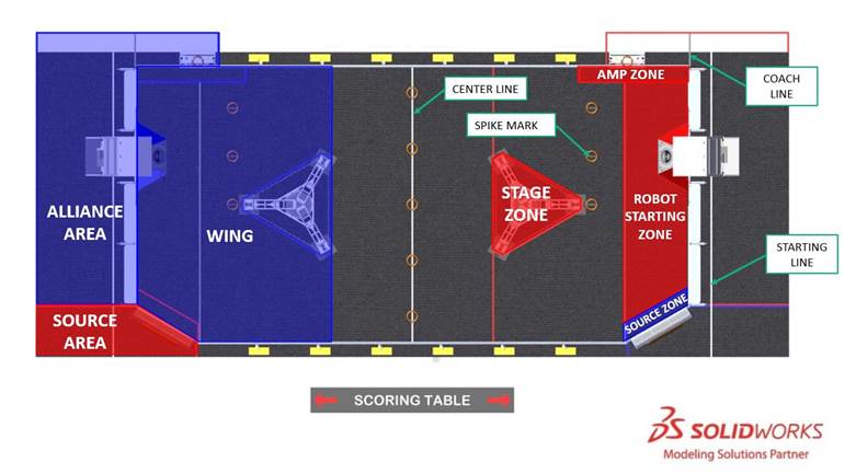
- : a 26 ft. 11⅛ in. wide by 9 ft. 10¼ in. deep (~821 cm by ~300 cm) infinitely tall volume formed by, and including theALLIANCE AREA, the edge of the carpet,ALLIANCE WALLcolored tape, guardrail, and theALLIANCEwall.AMP
- : a 10 ft. 10 in. long by 1 ft. 5¾ in. wide (~330 cm by ~45 cm) infinitely tall volume defined by theAMP ZONEwall, guardrail,AMP, and ALLIANCE-colored tape. TheALLIANCE WALLincludes the tape.AMP ZONE
- : a white line that bisects the length of theCENTER LINEFIELD
- : a black line in theCOACH LINEthat extends from the end of theALLIANCE AREA(ALLIANCE WALLside) to the edge of theAMPALLIANCE AREA
- : a 6 ft. 4⅛ in.-wide by 23 ft. 8⅛ in.-long (~193 cm by ~721 cm) infinitely tall volume bounded by theROBOT STARTING ZONE,ALLIANCE WALL, opponent’sAMP ZONE, and black tape. TheSOURCE ZONEincludes the black tape and excludes theROBOT STARTING ZONEandAMP ZONEtape.SOURCE ZONE
- : a 5 ft. ¾ in. wide by 15 ft. 10½ in. long (~154 cm by ~484 cm) infinitely tall volume bounded by theSOURCE AREAwall, the edge of the carpet, and ALLIANCE-colored tape. TheSOURCEincludes the tape.SOURCE AREA
- : a infinitely tall parallelogram shaped volume bounded by theSOURCE ZONEwall, the opponent’sSOURCE, and ALLIANCE-colored tape. TheALLIANCE WALLis 1 ft. 6¾ in. deep (~48 cm) with respect to theSOURCE ZONEwall and includes the ALLIANCE-colored tape.SOURCE
- : 1 of 11 1 ft. 1 in. (33 cm) marks used to identify placement ofSPIKE MARKbefore theNOTES. The 3 marks in front of eachMATCHare made with black tape, and the 5 marks along theSPEAKERare made with black marker (see Figure 6‑2).CENTER LINE
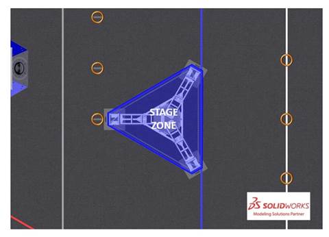
- : an infinitely tall 6-sided volume surrounding theSTAGE ZONEbounded by and including the ALLIANCE-colored tape.STAGE
- : a white line spanning theSTARTING LINEand adjacentALLIANCE AREAthat is parallel to and located 2 ft. (~61 cm) from the bottom square tube of theSOURCE AREAto the near edge of the tape.ALLIANCE WALL
- : an infinitely tall volume bounded by theWING, opponent’sALLIANCE WALLwall, guardrail, theSOURCEcolored line that spans the width of theALLIANCE, andFIELDwall. TheAMPincludes the tape.WING
5.3 AMP
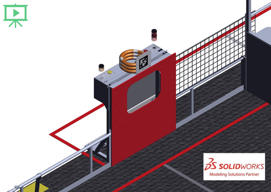
An
There are 2 sets of lights on top of the
The
- bottom light on: the has 1ALLIANCEtowards AMPLIFICATION (or Coopertition)NOTE
- both lights on: the has 2ALLIANCEtoward AMPLIFICATION (1 of which can be used for Coopertition)NOTES
- top light blinking at 2Hz: the isSPEAKER(see Section 6.5.3 AMPLIFICATION).AMPLIFIED
The Coopertition light behavior and meaning are as follows:
- blinking at 1 Hz: it’s or the initial 45 seconds ofAUTOand theTELEOPhas not used aALLIANCEfor CoopertitionNOTE
- solid on:
- o if initial 45 seconds of , theTELEOPhas used aHUMAN PLAYERfor CoopertitionNOTE
- o if after the initial 45 seconds of , bothTELEOPhave used aALLIANCESfor CoopertitionNOTE
- o if initial 45 seconds of
- off: the Coopertition window has expired, and Coopertition was not accomplished
A wire panel (Uline H6277BL) is horizontally installed to the top of the guardrail and between the
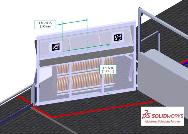
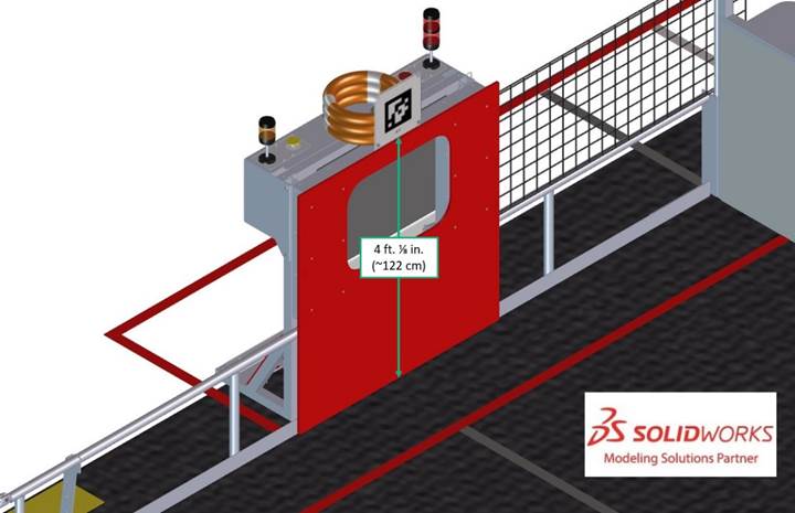
5.4 SOURCE
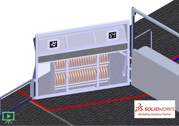
A
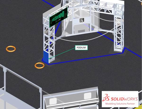
5.5 STAGE
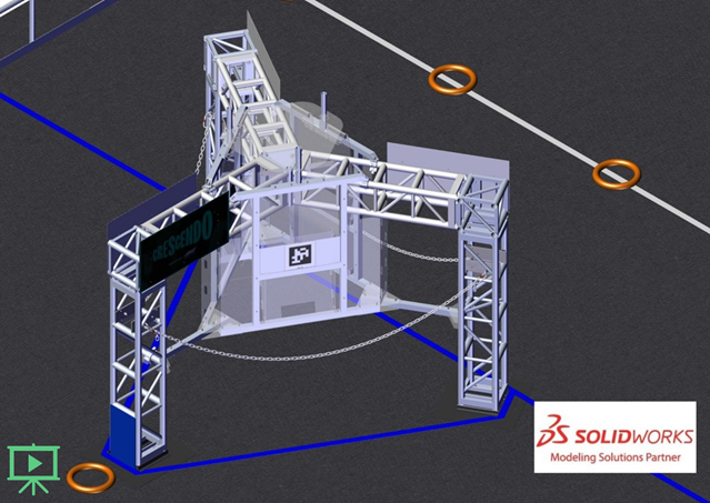
Each
3 chains, designated
The core structure of the

A
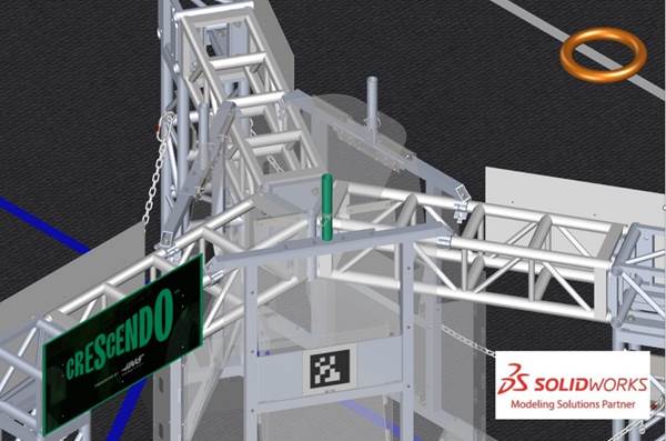
A
5.6 ALLIANCE WALLS
The
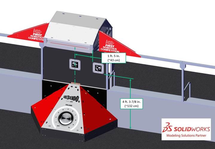
5.6.1 SPEAKER
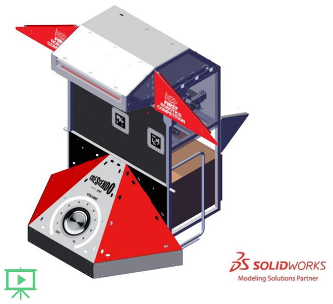
A
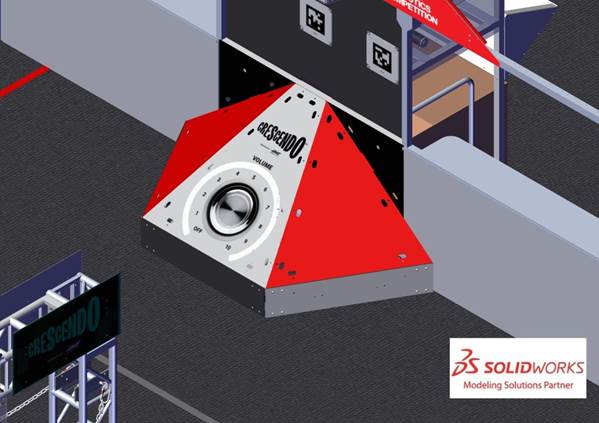
The SUBWOOFER is a 6-faced element centered below each
Lights indicate if the
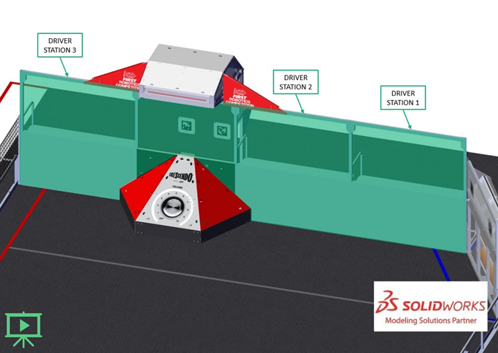
5.6.2 DRIVER STATIONS
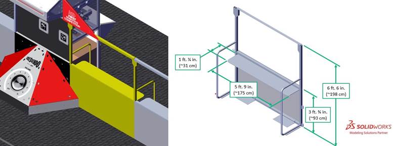
A
There may be a ramp available at events for
This ramp is available at many Regional and District events. For questions please connect with the local Program Delivery Partner.
Each
- 1 Ethernet cable: attaches to the Ethernet port of the and provides connectivity to theOPERATOR CONSOLEManagement System (FIELD)FMS
- 1 120VAC NEMA 5-15R power outlet (i.e. standard US outlet): located on each shelf and protected by its own 2-Amp circuit breaker. It can be used to power theDRIVER STATION.OPERATOR CONSOLEare responsible for monitoring their power consumption as a tripped breaker in the outlet does not constitute anDRIVE TEAMS. For some events in regions that don’t use NEMA 5-15 shaped outlets, event organizers may install appropriate plug adapters to be used throughout the event.ARENA FAULT
- 1 Emergency Stop (E-Stop) button: located on the left side of the shelf and is used to deactivate aDRIVER STATIONin an emergencyROBOT
- 1 Autonomous Stop (A-Stop) button: located on the right side of the shelf and is used to DISABLE aDRIVER STATIONduringROBOTAUTO
- 1 team sign: located at the top of each . TheDRIVER STATIONfacing side of the sign displays the team number in theFIELDcolor. TheALLIANCEside of the sign displays the following information in red:ALLIANCE AREA
- o Pre-MATCH: team number and connection stateROBOT
- o During the :MATCH
- o Pre-MATCH: team number and
- progress toward threshold (n/a during the Playoff Tournament),RP
- time remaining in AMPLIFICATION, and
- remaining period time.MATCH
- 1 timer (in 2 only): displays the official time remaining in theDRIVER STATIONperiod on the FIELD-facing side (in white) and official time remaining in theMATCHperiod andMATCHscores on theMATCHfacing side (in red).ALLIANCE AREA
- 1 team LED stack: indicates color,ALLIANCEstatus, E-Stop and A-Stop status, and is centered at the top of eachROBOT.DRIVER STATION
The stack includes 2 identical ALLIANCE-colored
- o status LEDsROBOT
- Solid: indicates that the is connected and enabled. This only happens during aROBOT.MATCH
- Blinking: indicates that either the is preset for theFMSand theMATCHis not connected yet, or it’s during aROBOTand the correspondingMATCHisROBOT, has lost connectivity, or the E-stop was pressed.BYPASSED
- Off: indicates that the is linked andROBOTprior to the start of theDISABLED. This light is also off, regardless ofMATCHconnection status, after theROBOThas concluded.MATCH
- o A-Stop/E-stop LED
- Solid: the isROBOTdue to a press of the team E-stop button, theDISABLEDE-stop button, or by the scorekeeper via theFIELD.FMS
- Blinking: the isROBOTfor the remainder ofDISABLEDdue to a press of the team A-Stop button.AUTO
- Off: the is notROBOTby theDISABLED.FIELD
- hardware and wiring: mostly located below shelves in the 2FMScloser to the scoring table.DRIVER STATIONS
5.7 GAME PIECES

A
A

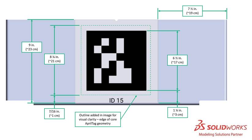
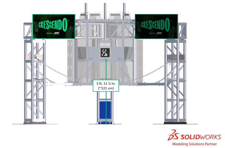
5.8 AprilTags
AprilTags are 8⅛ in. (~20 cm) square targets located above SUBWOOFERS, on
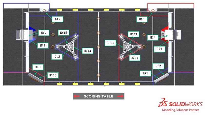
All markers are from the 36h11 tag family, IDs 1-16. AprilTags 1-10 are mounted to and centered on a 10½ in. (~27 cm) square polycarbonate panel; AprilTags 11-16 are mounted to an aluminum plate. Each marker has an identifying text label. If AprilTags experience wear and marking during

For further marker locating information please refer to the 2024
5.9 The FIELD Management System
The
When a
The
| Event | Timer Value | Audio Cue |
|---|---|---|
MATCH | 0:15 (for AUTO | “Cavalry Charge” |
AUTO | 0:00 (for AUTO | “Buzzer” |
TELEOP | 2:15 | “3 Bells” |
| Final 20 seconds | 0:20 | “Guitar Riff” |
MATCH | 0:00 | “Buzzer” |
MATCH | n/a | “Foghorn” |
5.10 FIELD STAFF
- Head – trains, directs, and supervisesREFEREE. They oversee all scoring processes and procedures in collaboration with the FIRST Technical Advisor (REFEREES). They interact withFTA, volunteers, and contracted/FIRST staff. The HeadSTUDENTSis positioned between theREFEREEand the scoring table and wears a yellow shirt. The HeadFIELDhas final authority for decisions regardingREFEREEscores, penalties, and YELLOW andMATCHassignments. For additional details, please refer to the HeadRED CARDrole description.REFEREE
- FIRST Technical Advisor () - ensures events run smoothly, safely, and in accordance with FIRST requirements. TheFTAcollaborates with FIRST staff, event staff, and other event volunteers in many different areas at events. TheFTAis the liaison between FIRST HQ and the event for all things related to theFTA,FIELD, and game, acts as a team advocate for all teams competing at the event, and is a major point of escalation and conflict resolution for the event. For additional details, please refer to theROBOTSrole description.FTA
- Supervisor - directs activity on theFIELDto ensure efficient execution of theFIELD, pacing of the event, and smooth flow ofMATCHESplay.MATCHSupervisors are responsible for ensuring theFIELDis intact and leadFIELDReset teams, who are responsible for resetting theFIELDafter eachFIELDin preparation for the subsequentMATCH. For additional details, please refer to theMATCHSupervisor role description.FIELD
<